India
India China
China Europe
 France
 Hong Kong
 Indonesia
 Japan
Japan Singapore
 Thailand
 USA
USA
UPS installation requirements
Requirements for UPS installation
Location
The UPS installation location should be chosen with care. The type and amount of site preparation required will vary according to the specific location and its relative location to the connected load. Preferably the UPS has to be installed close to the loads. If the distance between the load and the UPS is higher, we must consider the voltage drop based on the distance of the cable and suitable action like over sizing the cable needs to be considered.
Floor space requirements
It is important that adequate floor space has to be provided for the UPS. Check the dimensional information on the appropriate data sheets for the floor space requirements. The UPS equipment can be mounted with the back against a wall if rear access is not specifically required; however, if side and rear access can be maintained, it may be helpful should service become necessary. However, the requirement of rear clearance will be based on the construction of UPS. If the UPS is of modular construction, then a rear clearance is mandatory.
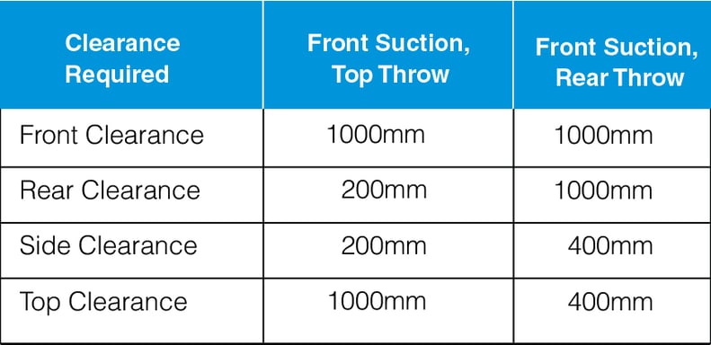
A clear area in front of the unit of at least 1meter should be maintained for service personnel.
.jpg?width=791&name=Chapter-24-01%20(1).jpg)
Figure 1-Typical Requirement of Clearance
Refer the below table for minimum clearance required
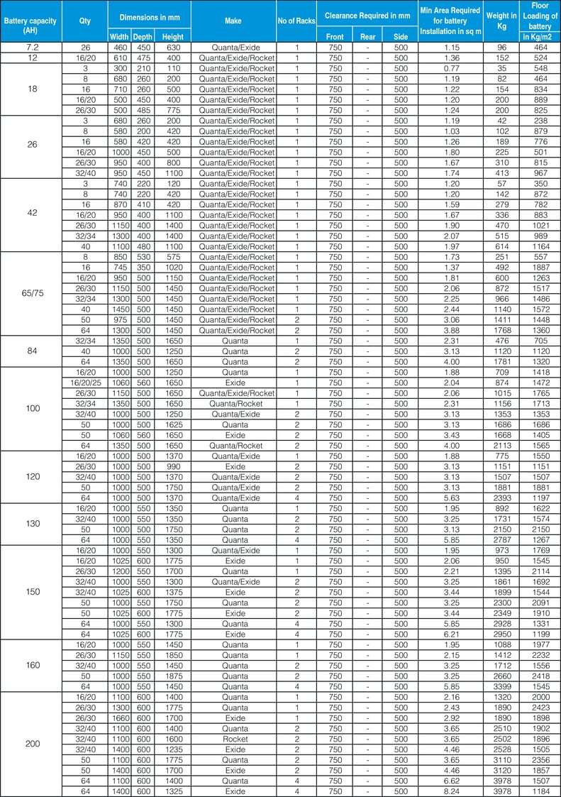
Care should be taken to assure that the floor loading capacity is sufficient to support the UPS and batteries. Floor loading of UPS will vary based on the capacity and the type of the UPS.
Most of the UPSs are designed for a maximum operating temperature of 40°C. The losses of the UPS is dissipated as heat and the UPS room should have the ventilation arrangement to remove the heat to maintain the ambient temperature below 40°C.The ventilation can be in the form of cross ventilation of hot & cold air (using air exchangers-inlet & exhaust fans with suitable filters) or with air conditioner.
It is also possible to install a duct either on the top side or the rear side of the UPS to suck out the heat produced by the UPS.
In order to provide for adequate ventilation, the UPS should be installed in a room, which has at least 1000mm of clearance on the top side or the rear side of the UPS based on the ventilation type. This area of UPS should be cleared of any obstruction, which would impede air flow. Since cooling air enters through a grill at the bottom front/front of the equipment, this area must also be kept clear of any obstructions.
UPS systems are designed to operate at full load in an ambient temperature of 0-40°C (32-104°F); 0-95% relative humidity; to altitudes of 1000m above mean sea level. However, as with all electronic equipment, operating over a prolonged period of time at elevated temperatures may be detrimental to the extended life of the equipment. In all probability, we would expect the normal temperature range to be between 25-35°C. Some installations may require that equipment be designed to operate at 50°C (122°F) for periods of time when normal cooling or ventilation has failed. High temperatures do have a negative effect on life of virtually all electronic components. For maximum service life, plan the equipment room so that normal operating temperatures are between 25-35°C. The UPS room should be relatively free of dust and dirt and other airborne contaminates as heavy layers of dust will reduce the cooling efficiency of the electronic components. It is important that the room low temperature control be adjusted to maintain the room temperature above the dew point in order to prevent condensation of moisture on the UPS. Also in areas of high humidity, UPS designed to operate under such conditions must be chosen or an adequate dehumidifier or precision air conditioner must be deployed to maintain humidity.
Requirement of air conditioner for UPS
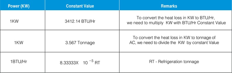
UPS system produces heat, which must be removed to prevent the UPS temperature from rising to an unacceptable level. Selection of air conditioner for UPS room requires an understanding of the amount of heat produced by the UPS. Heat is energy and is commonly expressed in Joules, BTU, tons, or calories. common measures of heat output rate for equipment are BTU per hour, Tons per day, and Joules per second (Joules per second is equal to Watts)
The selection of UPS for air conditioner has to be calculated based on
- Area of the room
- Number of persons who may utilize the room
- Sources of heat generation
- Insulation of the room
Sizing of air conditioner
Step 1:
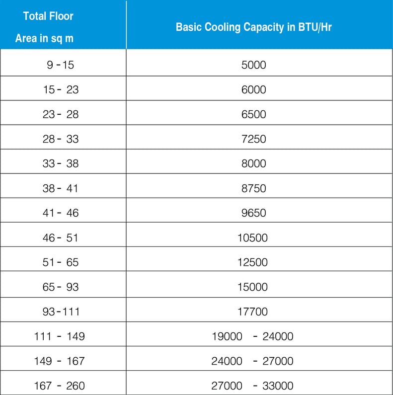
Multiply the length of UPS room by its width, which will gives us the total area of the room. Based on the below table, the basic capacity in BTU/Hr required for the UPS room can be calculated
Step 2: Arrive at the no of person who will work in the UPS room
Generally the UPS room is unmanned apart from the time when the technician visits to service the UPS or during the visit of maintenance engineer. It is ideal to consider 600 BTU/Hr per person to arrive at the air conditioner capacity of the UPS room.
Step 3: Heat Loss of UPS
To arrive at the capacity of the air conditioner required for UPS, we need to calculate the heat loss of UPS in KW using the formula
Heat Loss of UPS = Input Power in KW – Output Power in KW

Heat Loss of UPS = heat loss of UPS in KW x 3412.14 BTU/Hr (in BTU/Hr)
As a thumb rule, 7% of the UPS capacity can be considered as heat loss which gives the thumb rule formula of
Heat Loss in BTU/Hr = 7% x Capacity of UPS in KW X 3412.14 BTU/hr
Step 4: Insulation Loss
As a thumb rule, a 10% of insulation loss can be considered in the calculation
Sample Calculation – Capacity of Air Conditioner required for UPS Room
UPS capacity 200KVA
Area of UPS Room 9 sq m(3X3X3,WXDXH in m)
Heat loss of UPS 7%
Heat Loss of Other Loads 1%
No of Person in UPS Room 1
Insulation Loss 10%

Sample Calculation – Air Exchanges Required for Forced Ventilation of UPS Room
In the event, UPS manufacturers is not specifying the need of an air conditioner, adequate care must be taken to install inlet fans to bring in fresh air from outside the UPS room and exhaust fans to exhaust the hot air from the UPS room. The fans must have the required CFM to ensure the required air changes and should have filters to limit the dust in the UPS room.
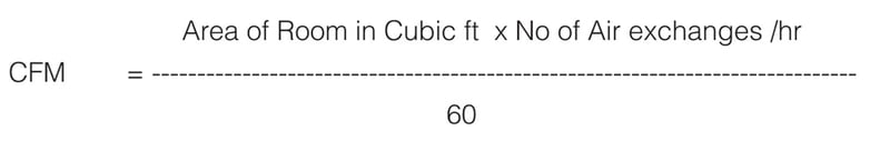
From the above formula, we can derive at the No of Air exchanges required to arrive at the capacity of fans required to remove the heat from the UPS room and to maintain a room temperature of less than 40°C. The number of air exchanges can be calculated from the below formula,
ds = CFM x 60
CFM calculated was 2400 and room size was 27m3 (952.7ft3)(from previous example)
The Fan arrangement & fan CFM must ensure 15 air exchange/hr in the room
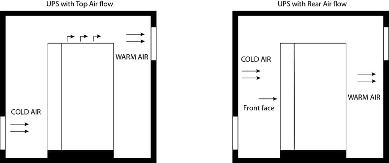
Figure 2 Cross Ventilation of UPS Room
Cable Sizing & Installation
It is imperative to select and specify the correct type and size of cabling in UPS installations. Failure to do so can result in overheating, fire risk and premature failure. It is also important to select the best method of installation alongside the most optimum routing. The same cable sizes should be installed for input and output and the selected cable should provide continuous full thermal current rating. A site survey will reveal the length of cable required and what voltage drop should be catered within the project specification and what size lugs are required.
General guidelines for cable routing & laying
Divide the power cables in groups like input cable, output cable and battery cable and bunch them together. A min of 10 cm clearance has to be provided between the cable groups as shown in the figure 3.

Figure 3 Typical Cable laying scheme
The control cables like UPS paralleling cable, communication cables like BMS, SNMP, battery monitoring, EPO needs to be grouped together separately and has to be laid separately to avoid any EMI/EMC issues. The control cables should be in a separate cable tray.
The cable tray for all cables has to be earthed.
Cable termination
The terminals for connecting the input, output & battery cables are located on the bottom of the UPS system and most UPS have bottom cable entry provision.
Taking into consideration of the minimum area available for cable entry and the bending radius, it is ideal to use single core flexible copper cables for terminating the input, output and battery cables.
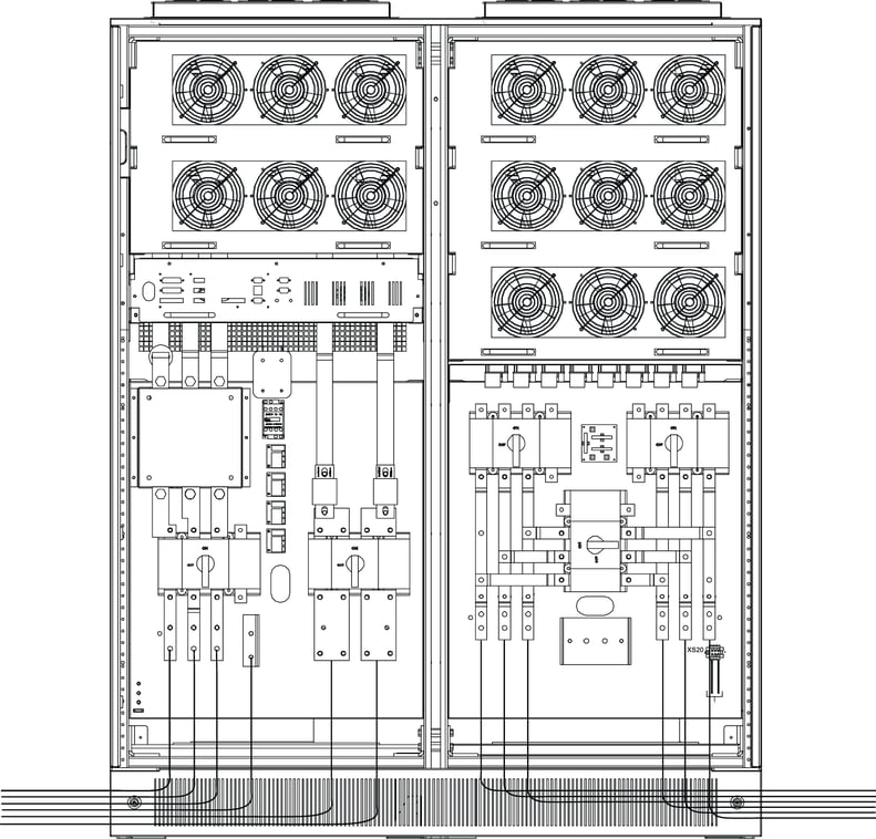
Figure 4 Termination of Cables with Single Core Flexible Cables
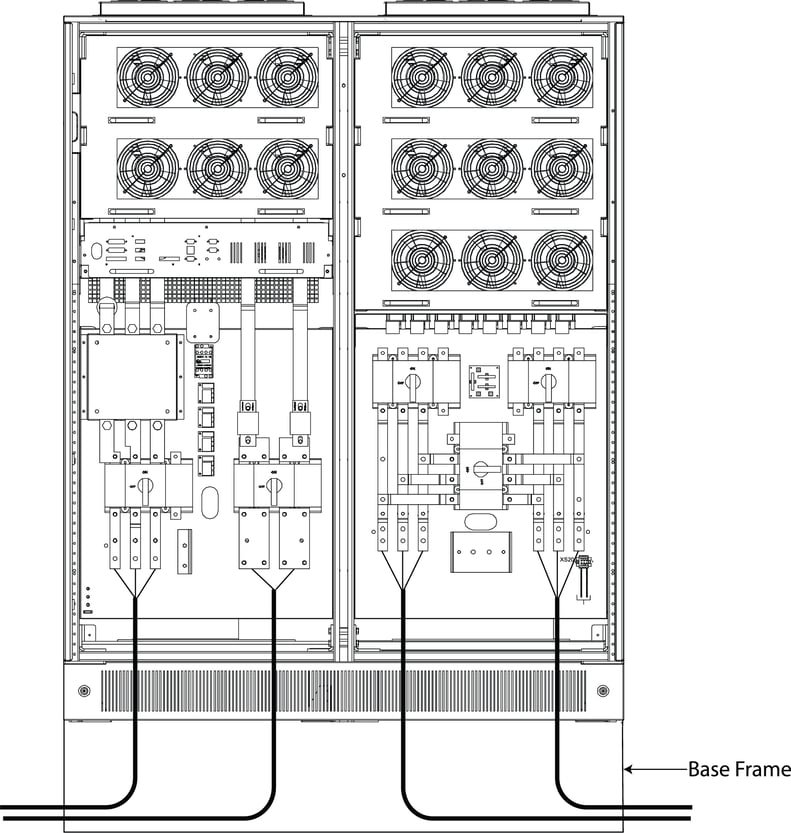
Figure 5 Installing of UPS with Armored Aluminium Cables
In case of usage of armored aluminium cables, the UPS system has to be installed on a elevated platform to get the necessary cable bending radius.
Electrical protection
Electrical protection with breakers or SFU (Switch Fuse Units) are important in two aspects
- To protect the other loads connected to the same distribution bus and to isolate the fault
- To protect the cables connected between the source and the loads.
It is recommended to have breakers or SFU(Switch Fuse Units with semiconductor fuses) at the input of the UPS. Protection in form of MCCB/MCB/fuses can be used in the downstream circuit while an isolator can be used at the output of UPS.
It is also recommended to have a split mains, a dedicated input breaker for input of the rectifier and a dedicated input for the bypass mains. This could avoid single point of failure. (figure 6)
Earthing
Earthing is very important for UPS as the fault current tends to flow through the earth back to mains to activate the protection system used in the circuit. Please refer Figures 8,9,10 on the earthing arrangement of the UPS.
In case of multiple UPS or parallel UPS configuration, all the UPS has to be connected together to the same earthing system.
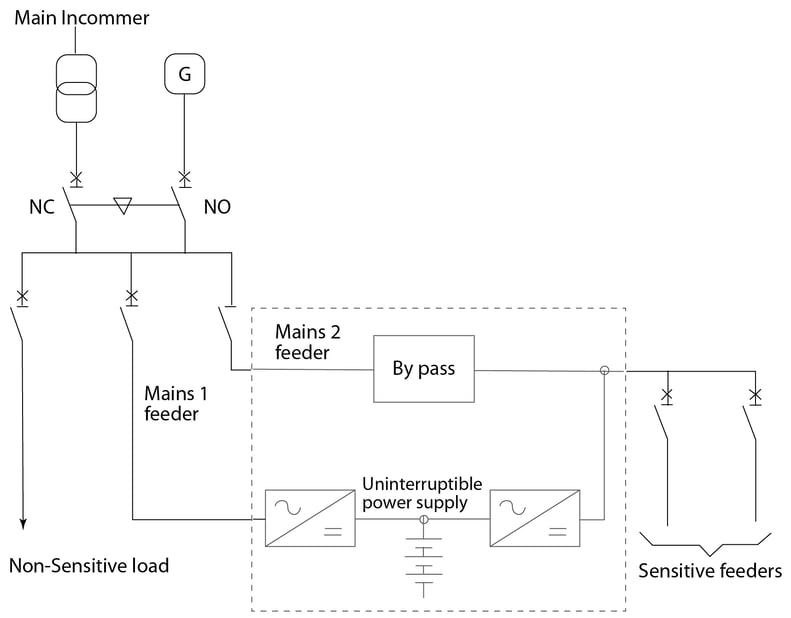
Figure 6 Typical Configuration of Dual Mains
Requirements for battery installation
Battery is the most unreliable component in the UPS and has the risk of fire and explosion if they are not managed properly.
The most common battery used in UPS system is SMF VRLA battery. These batteries produce Hydrogen gas during the
charging process and it combines with the oxygen inside the battery to form water. This process is called recombination. But however, under certain condition like overcharging of battery, the Hydrogen gas escapes from the container though the safety vents. If the Hydrogen content is more than 4%, then the atmosphere becomes a combustible environment.
This has paved way for special considerations of battery installation and is regulated as per IEEE – 1187 recommended practice for installation of valve regulated Lead-acid batteries same as equivalent practice for wet cells
Battery room consideration
Ideal recommendation is to have a separate room for installation of battery with the consideration of the following points
- Flame retardant doors
- The electrical installation in battery rooms should be limited to:
- Lighting
- Ventilation
- Smoke detectors may be installed in battery rooms along with hydrogen detectors. Fan operation may be interlocked with hydrogen detector actuation and the same can also be linked with the EPO of UPS system, so that in the event of hydrogen gas accumulation, the UPS can be switched off and the charging process can be stopped.
- The room ceiling should be flat to ensure that pockets of trapped Hydrogen gas do not occur, particularly at the ceiling, to prevent the accumulation of an explosive mixture,
- Light fittings should be fixed to the wall or suspended at more than 50 cm from the ceiling, but not vertically above the batteries or charging units.
- Light fittings as well as any other equipment should be of closed type to prevent accumulation of gas.
Battery rack consideration
Ideally battery is recommended to be installed in a open rack rather than a closed cabinet as the closed cabinet will have disadvantages like
Access for installation
- Difficult to make and inspect connections and check torque
- Access for maintenance.
- Difficult to access terminals to take periodic readings.
- Visual inspection is impossible.
- Replacing defective battery blocks can be extremely difficult.
Heat
- Heat generated by nearby equipment.
- Heat buildup because of restricted air flow
- Heat generated within the battery because of charging current Personnel safety.
- It can be plain dangerous
Ventilation
Ventilation of the battery room is an critical point for the safety of the installation. If there are not proper ventilation then an accumulation of hydrogen gas in the battery room could lead to fire in the installation.
The ventilation requirement of VRLA battery is defined in EN 50272-2.
The purpose of ventilating a battery location or enclosure is to maintain the hydrogen concentration below the 4 %vol Hydrogen Lower Explosion Limit (LEL) threshold. Battery locations and enclosures are to be considered as safe from explosions, when by natural or forced (artificial) ventilation the concentration of hydrogen is kept below this safe limit.
The minimum air flow rate for ventilation of a battery location or compartment shall be calculated by the following formula:
Q = v x q x s xn x Igas xCrtx 10-3 [m3/h]
Where:
Q = ventilation air flow in m3/h
v = necessary dilution of Hydrogen
(100% -4%)/4% =24
q = 0.42×10⁻³ m3
/Ah generated Hydrogen
s = 5 , general safety factor
n = number of cells(2V)
Igas = current producing gas in mA per Ah rated
capacity for the float charge current Ifloat or the
boost charge current Iboost
Crt = capacity of the battery
Igas = 1 for VRLA Battery
Igas = 5 for Vented Battery
Igas = 5 for Ni-Cd Battery
With v • q • s = 0,05 m3/Ah the ventilation air flow calculation formula is:
Q = 0,05 • n • Igas • Crt • 10-3 [m3/h]
The amount of ventilation air flow shall preferably be ensured by natural ventilation, otherwise by forced (artificial)ventilation. Battery rooms or enclosures require an air inlet and an air outlet with a minimum free area of opening calculated by the following formula:
A = 28 • Q
with Q = ventilation flow rate of fresh air [m3/h]
A = free area of opening in air inlet and outlet [cm2]
NOTE: For the purpose of this calculation, the air velocity is assumed to be 0.1 m/s. The air inlet and outlet shall be located at the best possible location to create best conditions for exchange of air i.e, exchange of air, i.e.
- openings on opposite walls,
- minimum separation distance of 2 m when openings are on the same wall.
SMF VRLA battery are designed for an operating temperature of 25-27°C, it is important to ensure that same with proper sizing of air conditioner to maintain the temperature in the battery room.
The heat loss of the battery under normal float conditions is too low, the air-conditioner has to be sized based on the room area, latent heat and the air exchanges required.
Heat loss of the battery in float mode is calculated with the voltage and trickle charging current
Heat loss of battery = V X Itrickle
Itrickle = 1mA/AH ie.for 100AH it is 10mA
The calculation is almost similar to that of the UPS room.
Air exchanges required for Battery Room (Only for SMF VRLA Battery)
The air conditioner for battery is designed based on the heat loss during float conditions and the flow rate of fresh air [m3 /h] required to limit the hydrogen content in the atmospheric air to less than 4%.
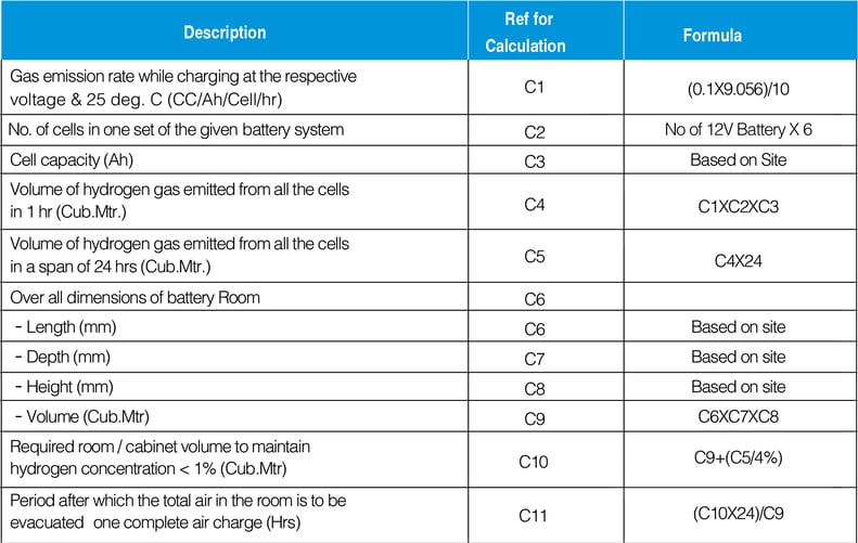
The air exchanges required can be calculated using the formula shown in Table 2
Sample Calculation
The sample calculation is based on the below considerations
Battery capacity – 150AH
No of battery – 50 Nos of 12V Block
No of cells in each block – 6
Trickle current – 1mA/AH
Area of room – 4.25m2
Sample Calculation 1: Required Airconditioner Capacity
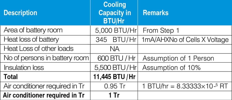
Table 2 Formula for Calculation required nos of Air exchanges in battery room
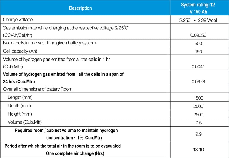
Sample Calculation 2 Required Nos of Air exchanges in Battery Room
Battery protection
Battery protection and cable
The battery protection has to be installed close to the battery, preferably in the battery rack or in a separate enclosure close to the battery.
In case of multiple battery banks of used, it is ideal to have a common isolator with fuse or an MCCB and an individual battery isolator for each string of battery
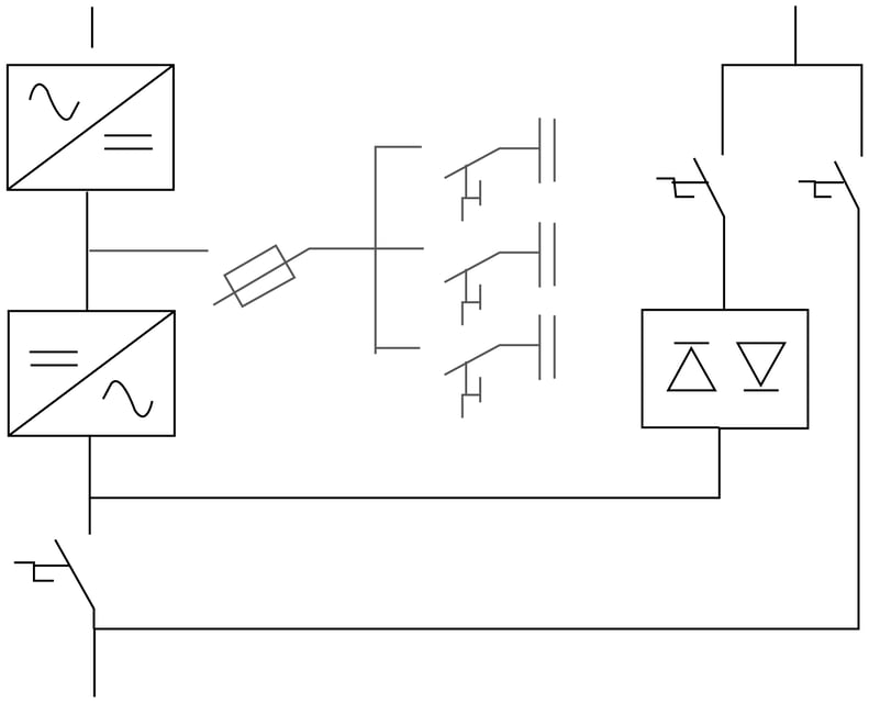
Figure 7 Typical Schematic of battery protection
The diagram shown below, shows the earthing arrangement of an Transformerless UPS and its battery rack.
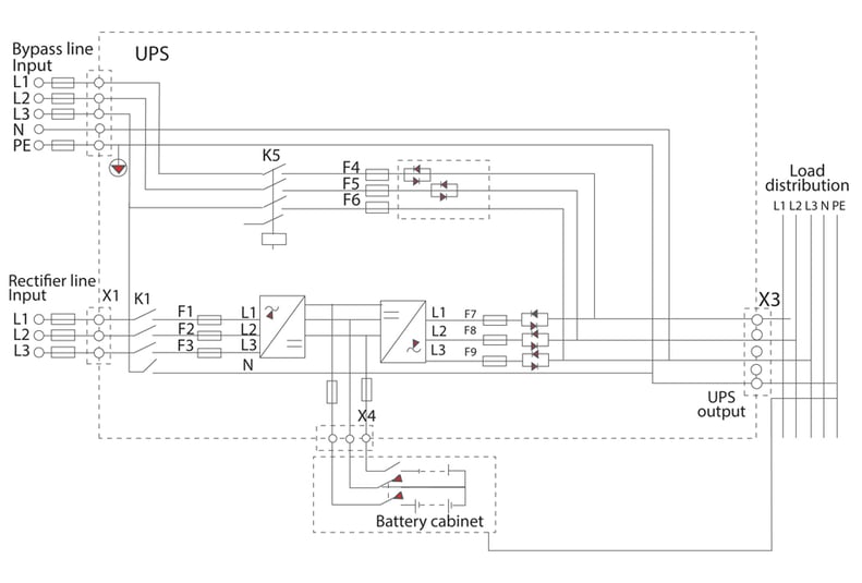
Figure 8 Earthing arrangement of Transformerless UPS (TNS System)
The diagram shown below, shows the earthing arrangement of an Transformer based UPS with
bypass enabled and its battery rack
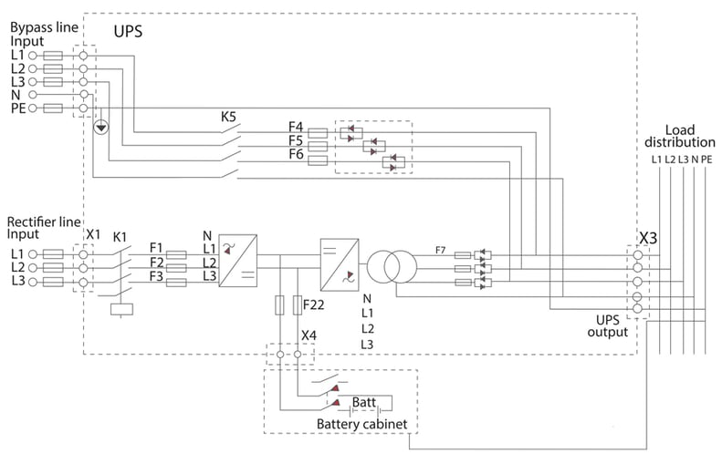
Figure 9 Earthing arrangement of UPS with Inbuilt Transformer and bypass Enabled(TNS System)
The diagram shown below, shows the earthing arrangement of an Transformer based UPS and its Battery rack. The UPS is acting as a separately derived source as the bypass is disabled and the transformer neutral is earthed.
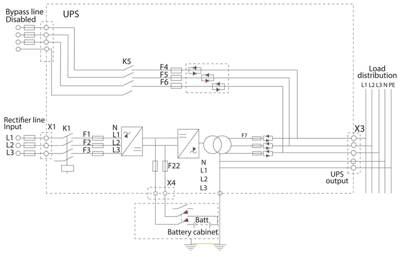
Figure 10 Earthing arrangement of UPS with Inbuilt Transformer and bypass Disabled(TNS System)
Quick reference battery selection
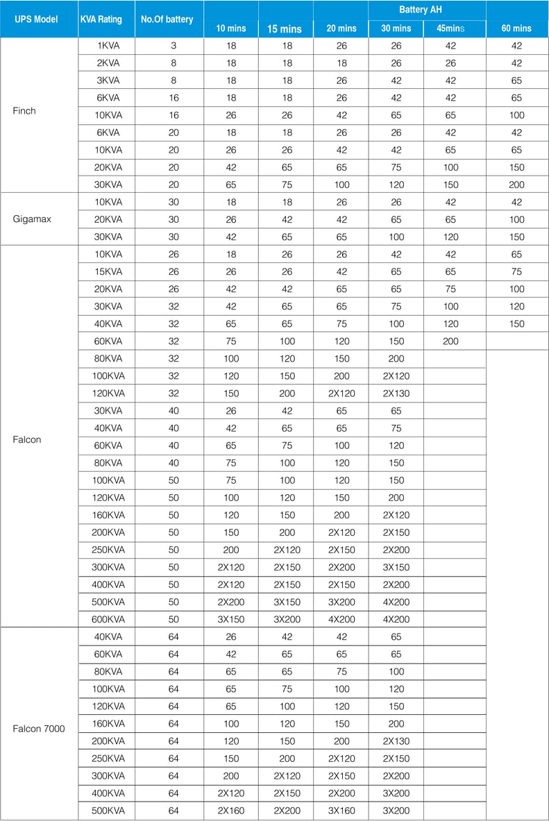
Note:
The battery sizing is based on output Power factor of 0.8 with an cutoff Voltage of 10.5V/Battery This is only for reference and has no obligation of the company. The battery capacity can vary based on sizing considerations and battery make ageing factor & design margin are not considered in the battery sizing.
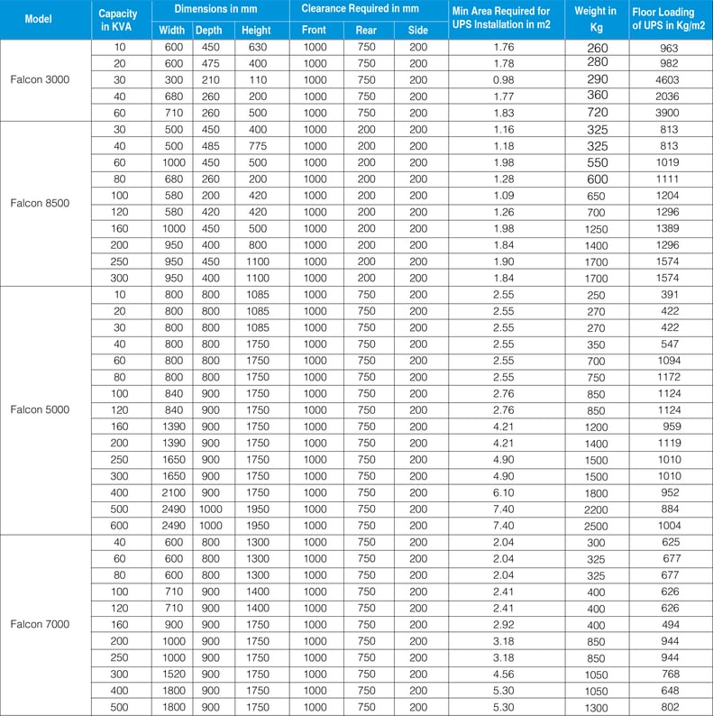
Area required for UPS installation
Area required for battery rack installation