 India
India China
China Europe
 France
 Hong Kong
 Indonesia
 Japan
Japan Singapore
 Thailand
 USA
USA
Reliable power for hospitals and healthcare facilities
When people think of high-reliability facilities, most often it is the financial data centres and the semiconductor plants that come to mind. While these types of facilities can experience very costly downtime, hospitals and other healthcare facilities handle a far more valuable “product” called Human life.
Hospitals are highly dependent on sophisticated electronic equipment in laboratories, intensive care units and even for administrative tasks being carried out by the medical staff at the hospital bed. What is the price tag for data corruption that results in the wrong medicine request being formulated in the pharmacy or loss of access to EKG or other diagnostic imaging equipment during a procedure and other patient monitoring equipment at the nurse’s station in the Intensive Care Unit (ICU) or loss of power to the Operating Theatre (OT) room during a transplant procedure? You can’t put a price on poor power quality.
Common sources of power quality problems
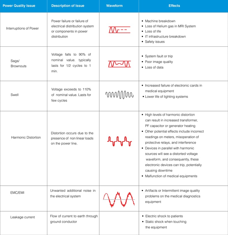
The healthcare environment comprises of various combination of sensitive electronic loads and other commercial loads. Hence maintaining quality power is essential and critical. Power quality is the term used for overall voltage quality, current quality and nature of output waveform, which directly or indirectly affect the various loads in a hospital. As the medical devices are sensitive, poor quality power affects their performance. Electrical disturbances will lead to lock up or shutdown of the devices. Power quality problems may arise due to non-linear loads inside the Healthcare Facility resulting in injection of harmonics and interaction between medical equipment’s.
Common sources of power quality problems found in hospitals include
Common sources of power quality problems found in hospitals include
- Incoming Mains Power Quality
- Inadequate wiring and grounding
- High wattage diagnostic imaging equipment
- Testing of emergency generators
- Physical plant renovation
Since power quality problems are cumulative; small power quality events can cause premature and frequent equipment failures and also may lead to loss of life.
Common symptoms of power quality (PQ) problems in a healthcare facility
- PQ problems are often mistakenly identified as software “bugs”.
- PQ problems are often mistakenly identified as “normal” hardware failures.
- Frequent downtime for Diagnostic Imaging Equipment like X-Ray, Cath Labs, CT, and MRI systems.
- Equipment locks up or halts during operation.
- Unexplained system error log entries.
- Data transmission errors.
- Repeated service calls where the same sub-assemblies have recently been replaced.
- Static shock when touching the equipment.
- Power supply and circuit board failures.
- Premature X-Ray tube failures.
- Intermittent image quality problems.
- Equipment disruptions and failures during or after generator testing.
- Problems restarting equipment after lightning storm or power outages.
- Problems occur at a specific time of day of the week or time of the year.
- Problems occur after adding a new element to the system.
Impact of power quality issues
Medical locations classification
Medical locations are classified by IEC 60634-7-710 according to the use of “applied parts”. An applied part is a piece of electrical equipment that is brought into physical contact with the patient, or might come into contact with the patient or needs to be touched by the patient.
The classification is as follows:
1. Group 0: Medical locations without applied parts.
2. Group 1: Medical locations where applied parts are used externally or invasively to any part of the body, except for the locations described in group 2.
3. Group 2: Medical locations where applied parts are used in applications such as intracardiac procedures, operating theatres, and vital treatments where discontinuity of the supply can cause danger to life.
Class refers to the maximum break in time with in which an emergency power supply must be operational after a power failure.
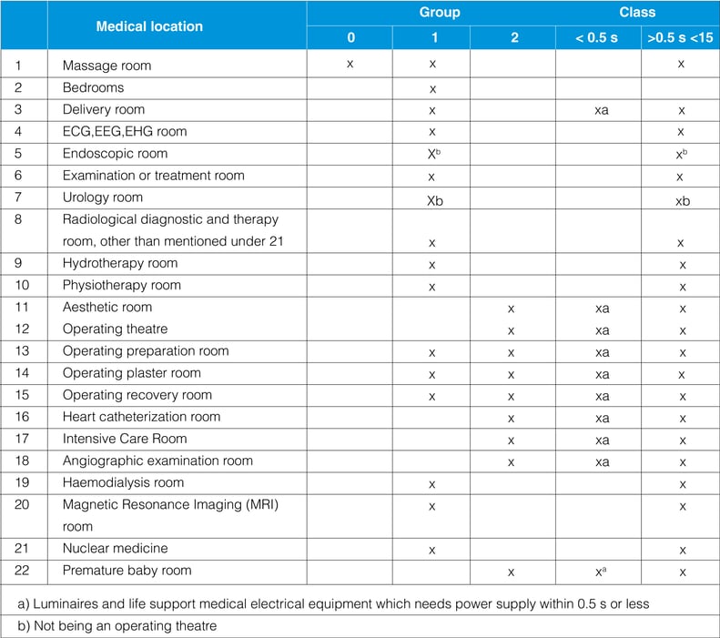
Classification of safety power supply for medical locations with reference IEC60364-555
Class 0 –Automatic supply available
Class 0.5 – Automatic supply available within 0.5s
Class 15 – Automatic supply available within 15s
Emergency or safety power supply
Regarding the continuity of power supply in medical locations, emergency or safety power supplies are classified on the basis of changeover time (when there is a mains power issue) as required by the service or end equipment they support:
1. Power supplies with a changeover period less than or equal to 0.5 seconds: Secure power supply which is capable of maintaining operating theatre table lights, critical medical equipment, and other essential luminaries for a minimum period of 90 minutes and with a changeover period not exceeding 0.5 seconds. The best emergency power solution to provide backup power within 0.5 seconds after a power failure for Group 2 locations is a UPS (Online) or Inverter (Offline UPS) (UPS – Uninterruptible Power supply with a battery back-up).
2. Power supplies with a changeover period less than or equal to 15 seconds: Secure power supply for equipment which must be connected within 15 seconds for a minimum period of 24 hours, when the voltage of one or more line conductors at the main distribution board for the critical services has decreased by more than 10% of the nominal value of supply voltage for a duration greater than 3 seconds. The best emergency power solution to provide power conditioning within 15 seconds during voltage fluctuations for Group 1 and Group 2 is an automatic voltage regulator or Servo-Controlled Voltage Stabilizer.
3. Power supplies with a changeover period greater than 15 seconds: Used for equipment required for the maintenance of hospital services, which may be connected either automatically or manually for a minimum period of 24 hours. This includes, for example, sterilization equipment, air conditioning, heating, and ventilation systems. The best emergency power solution to provide a long term back-up for Group 0, 1, and 2 locations in the event of a prolonged power failure is a backup generator (DG Set).
Use of UPS for critical applications and equipment
Use of UPS (Uninterruptible Power Supply) for critical applications and equipment within a healthcare facility
Mains failure can be simply overcome by incorporating an UPS System in the electrical distribution. Critical applications like OTs, emergency lighting, IT infrastructure across the hospital and diagnostic imaging equipment’s have to be protected by a UPS to provide uninterruptible power and as an emergency power backup system.
Which is a better strategy for your UPS system: centralized or distributed?
Choosing the right UPS to suit the needs of different applications is a major task. Power requirements vary according to the type of application (such as critical or non-critical), kind of equipment being protected and the environment it has to be placed in. Moreover, factors such as life cycle costs, reliability, manageability and serviceability among others must be taken into account before installation.
Centralised UPS configuration is a system where the UPS is installed in a centralised location like electrical panel room and then the power is distributed across the hospital catering to all types of loads like lighting, diagnostic imaging systems, laboratory etc.
Distributed (Decentralised) UPS configuration is a system where a dedicated UPS is installed near to the loads for a specific applications like a dedicated UPS for MRI machine, dedicated UPS for IT infrastructure, dedicated UPS for OT, ICU etc.
Comparison of centralized and De-centralized UPS architecture
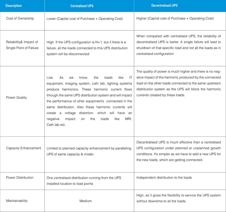
The decision to have a centralized or decentralized UPS protection is extremely critical as both the configurations of UPS have their own merits and shortcomings. The choice depends on the needs and requirements of individual applications. In the case of a hospital or healthcare facility, a segmented UPS distribution will provide the most optimum solution.
- Centralised UPS (On-line) for all IT applications.
- Centralised (Off-line UPS) inverter for of all facilities emergency lighting.
- Decentralized separate UPS for ICU, OT and each individual diagnostic imaging equipment.
The mix of centralized and decentralized UPS provides a good balance between cost and reliability in a healthcare facility.
Optimizing availability of UPS
Optimizing availability of UPS for different applications in a hospital:
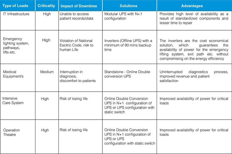
For mission critical applications like operation theatres, ICU’s & IT infrastructures, redundancy has to be incorporated in the UPS electrical system to avoid single point of failure.
To improve the availability of power for critical applications, it is important to
- Add redundancy.
- Minimize chance for human error.
- Minimize downtime.
- Standardize service concept.
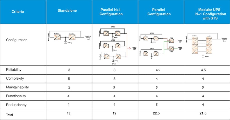
Ways to improve availability with different UPS configurations
Configurations of UPS
The following table is a presentation of four typical UPS configurations used in Healthcare facilities and an evaluation of each of their capabilities.
A score of “5” indicates the highest degree of criteria capability, while a score of “1” indicates the lowest degree of criteria capability.
Special considerations for UPS
Mains line resistance (MRM)
Due to high step load nature of CT, cath lab and MRI equipment during the scanning process, it is necessary that source impedance shall be minimum so that the resultant voltage drop due to the high current does not affect the performance of the diagnostic equipment during the scan.
In case supply source is from mains or genset, the line or mains mmpedance or resistance can be measured with special meters such as mains line resistance tester. Basically, this meter injects high impulse load and measures the resulting voltage drop and displays it in terms of line resistance. The target mains impedance based on this measurement should be less than 150-200 milliohms so that during a scan there is no appreciable drop in voltage at the input of the end equipment like a CT or MRI machine.
Harmonic distortion
Harmonics have become a greater concern as now a days there are a wide range of biomedical equipment’s which draw high impact current and power and then inject back the non-sinusoidal current to the electrical supply systems. Among those kinds of equipment’s are Magnetic Resonance Imaging (MRI), Nuclear Magnetic Resonance Imaging (NMRI), Ultrasound machine, Computerised Axial Tomography (CT) scan, laser surgery equipment, x-ray machines, Gamma camera, etc. In addition to the harmonics pollution from biomedical equipments, there is also great harmonics coming from IT/data support system, UPS, Lighting and Lighting Control Systems (e.g. LED and CFL lamps), some of HVAC systems as well as Variable Speed Drives (VSD) for lifts and escalators.
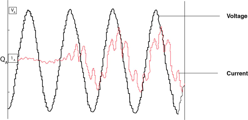
Figure:1 Current Drawn by Diagnostic Imaging Equipment during scan is highly non-linear and rich in harmonics
The effect of harmonics might include the malfunctions in biomedical equipment such as distortion of displays due to distorted voltage, equipment lockup, control/alarm and malfunction due to microprocessor malfunction. Excessive Electromagnetic Compatibility (EMC) effects of harmonics might cause disturbance and interference to telecommunications systems and other healthcare equipments.
Ways to reduce harmonics effects
Tackling harmonics by reducing the level of harmonics at their source by limiting harmonic distortion from harmonics generating equipment has been argued as one of the most effective ways in reducing the level of harmonics pollution in general power systems. This might be a sound solution for Healthcare facility as the health care equipment could be chosen as such that only equipment with the lowest level of harmonics distortion are installed. However, it is apparent that initial cost of acquiring such equipment with our harmonics might not be financially viable.
Another approach which might increase the immunity of the healthcare electrical supply systems to harmonics is from the improvement of supply transformer as well as from the conductors. Derating of transformers or over sizing the transformers, giving a transformer an appropriate K- factor rating, as well as oversizing the neutral conductor to account for additional heating and load loss as a result of harmonics might help to improve the immunity of the electrical power supply systems. However, the larger conductors to oversize transformers as well as neutral might not be technically feasible and also might not necessarily be an economic solution.
The best solution for an existing facility is to use a passive or active harmonic filter to mitigate the effect of harmonic producing loads.
Electromagnetic interference
Medical equipments utilized in medical facilities can act as EMI sources. Some of the more prominent of these are listed below:
- Life support equipments such as ventilators, cardiac defibrillators, and infusion pumps.
- Patient telemetry and assistance equipments which includes electrocardiographs and motorized wheelchairs.
- Electrical surgical units and their associated support equipments.
- Magnetic Resonance Imaging (MRIs) systems.
- X-ray units, both therapeutic and diagnostic.
- Gamma Beam Electron Accelerators and therapeutic equipments.
The major challenges faced on account of electromagnetic interference are artifacts or intermittent image quality problems in the medical diagnostics equipment.
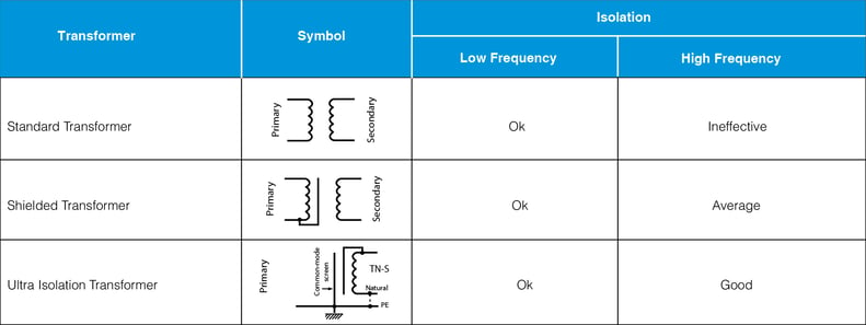
Ways to reduce electromagnetic interference using isolation transformers
System earthing and safety requirements
in each medical location of group 1 and group 2, supplementary equipotential bonding conductors must be installed and connected to the equipotential bonding bus bar for the purpose of equalizing potential differences between protective conductors and extraneous conductive parts located in the “patient environment”.
In group 2 locations, the IT earthing arrangement (referred to as “medical IT”) must be used for circuits supplying medical electrical equipment and systems intended for life support, surgical applications, and other electrical equipment located in the “patient environment”.
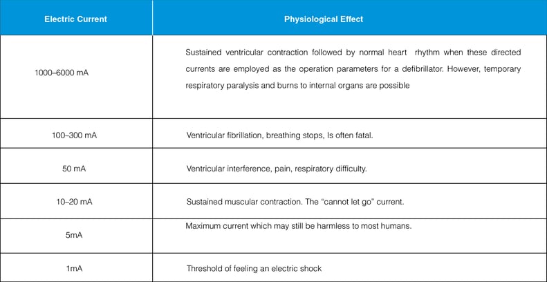
Leakage current
Electric equipment operating in the patient vicinity, even though operating perfectly, may still be hazardous to the patient. This is because every piece of electrical equipment produces a leakage current. The leakage consists of any current, including capacities coupled current, not intended to be applied to a patient but which may pass from exposed metal parts of an appliance to ground or to other accessible parts of an appliance.
Normally, this current is shunted around the patient via the ground conductor in the power cord. However, as this current increase, it can become a hazard to the patient. Without proper use of grounding, leakage currents could reach values of 1,000 µA before the problem is perceived.
Leakage current is a critical aspect for safety of patients in
- Intensive care units (ICUs)
- Coronary care units (CCUs)
- Emergency departments
- Special procedure rooms
- Cardiovascular laboratories
- Dialysis units
- Various wet locations
Protection from leakage current
Ways to protect patients from leakage current
The Isolated Power Supply (IPS) is the recommended solution as per IEC 60364-1-710.The IPS is an IT system, an isolation transformer is used to isolate live and neutral from earth. The socket earths are connected to an equipotential earth reference bar as recommended in IEC 60364-1-710. The additional equipment needed to complete the minimum IEC requirements is an insulation monitor and visual/acoustic alarm unit.
The earth is isolated from both lines in an Isolated Power System. If a dead short to earth or a leakage current occurs, the circuit breaker will not trip and therefore continuity of supply for the patient monitoring or life support equipment will be maintained.
Also, because the earth is isolated, resulting in a very high resistance to earth, any patient or staff accidentaly touching a line will only experience safe values of capacitive return current. The IPS monitors has an insulation monitoring device and triggers an alarm when a leakage current is present in the distribution system of IPS.
Consul Neowatt Solutions
To Mitigate Power Quality Issues in Hospitals
Servo Controlled Voltage Stabilizer (Automatic Voltage Regulator)
Consul Neowatt is the No.1 Automatic Servo Controlled Voltage Stabilizer Brand in India and comes with an industry leading 5 years Warranty. The stabilizers are rugged and proven over 30 years across thousands of Hospitals in India and abroad.
- Air cooled stabilizers are available in natural and forced air cooled in a range from 3 – 500 KVA used
for individual diagnostic imaging equipment or complete Healthcare facilities. - Oil cooled stabilizers are available in a range from 3 – 3500 KVA for voltage protection of entire
Hospital.
Ultra-Isolation Transformer
- Split winding constructions and bi-filar connections is made to reduce the overall capacitance of the winding
- High insulating materials and special shielding techniques have been used to minimise the noise
- The core and its magnetic properties are chosen in a way that displays enough leakage inductance, so that the higher frequencies are blocked
- Transfer of electric noise is blocked by Unique Box shielding
- Better regulation with low impedance effect
- Shield against strong lightning, impulse noise, bus short circuit, accidental discharge of capacitors, etc.
- Shield for the microprocessor-based medical machines and equipment’s from damage due to electrical noise, spikes etc.
Isolated Power Supply
The medical isolation panel is designated for use in group 2 locations as per
- IEC 60364 Part 7-710: Requirements for special installations or locations – Medical locations
- National Electric code 2011(SP 30:2011), Section 4, Medical Establishments Group 2 Medical Locations are
- Operation Theatre
- Operation Preparation Room
- Operation Plaster Room
- Operation Recovery Room
- Intensive Care Unit
- Heart Catheterization Room
- Angiographic Examination Room
- Premature Baby Room
Pelican Offline UPS (Inverter)
The medical isolation panel is designated for use in group 2 locations as per
- Intelligent high efficiency power backup solution for lift and lights (98-99% Efficiency).
- Classified as VFD topology(IEC 62040-3)
- Transfer time of <5ms
- Inbuilt galvanic Isolation between battery and Load
- Available 10 to 600KVA
Falcon Online Double Conversion UPS
- Modular Construction
- Horizontal and Vertical Paralleling
- IGBT Based Rectifier and Inverter
- Latest generation 32-bit floating-point DSP controller design
- Advanced Thermal Management
- CAN Bus Communication
- Fan Redundancy
- Long Life AC Capacitors
- Multi-colour TFT Screen(optional)
- Proven solution for hospital infrastructure, IT & Diagnostic imaging loads
IORA Active Harmonic Filters
- Modular construction, most unique design concept
- Based on Floating point 32 bit DSP
- Selective harmonic elimination methods. CT can be connected in load as well as in source
- Ethernet based Remote monitoring and 7 inch SVGA touch screen display
- Compact in size
- Internal CAN communication
- Employs high speed IGBTs in power circuit
- Closed loop active filter with source current sensing
- High attenuation up to 96% of individual harmonics
- Programmable selective harmonic elimination
- PF compensation, leading as well as lagging
- Load balancing
- Helps in achieving the compliance with power quality regulations like IEEE 519