 India
India China
China Europe
 France
 Hong Kong
 Indonesia
 Japan
Japan Singapore
 Thailand
 USA
USA
Key components of online double conversion UPS
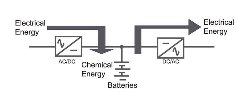
A double conversion UPS converts the incoming alternating current (AC) to a direct current (DC), so it can power the system’s battery, and then inverts the DC back to AC for powering equipment –hence the name “double conversion.” Take a look at how a UPS’s components work together so you can better understand your system and ensure your mission critical load remains online.
The UPS system acts as a source to the loads connected to it and as a load to the electrical mains.
Rectifier
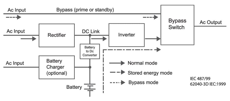
Figure 1 Double Conversion UPS
As shown in the above figure, an online double conversion UPS has 4 major components
- INVERTER
- BATTERY
- STATIC SWITCH
- RECTIFIER
The rectifier acts as a load to the electrical mains. The primary objective of the rectifier is to
a) Convert the incoming power supply (AC) to DC
b) Charge the battery
It also has a hidden objective which is to draw a sinusoidal current from the mains and also to ensure the current drawn is in phase with the voltage waveform so that the current harmonic distortion injected on the mains is less and the power factor is better.
The rectifier in a three phase UPS is designed to operate under nominal input voltage of 415V and frequency of 50Hz. Taking into consideration voltage fluctuations, the rectifier is typically designed to operate with a input specific voltage range of ±15% and frequency range of ±6%.
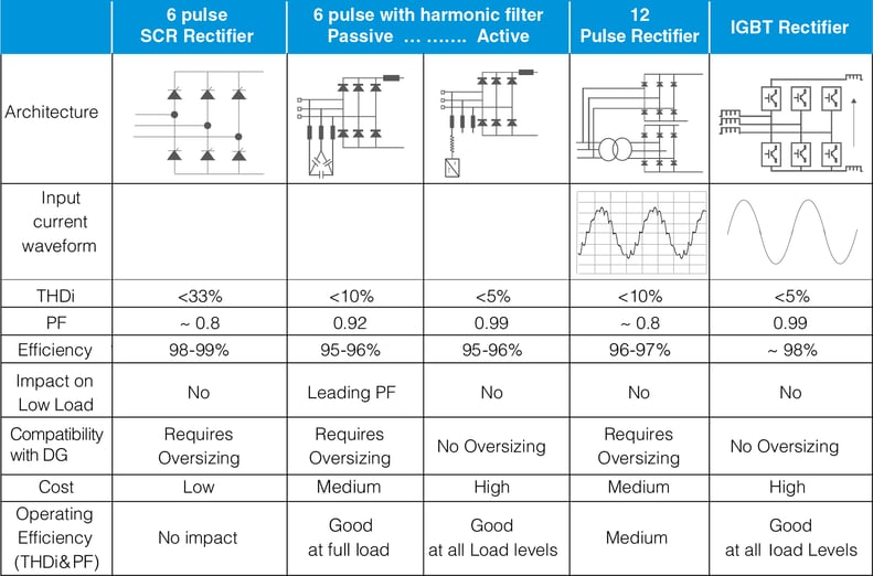
In general the best rectifier topology should have high efficiency, high power factor (PF) and low current distortion(THDi).This will ensure good compatibility with Genset and also reduce the need to oversize the DG set, incoming transformer and cable sizing for supporting the UPS.
The technology of the UPS has evolved and different technologies are being used in the rectifier of the UPS. A short comparison of different rectifier technologies is given in the table below.
Inverter
The primary objective of the inverter is to convert DC power to AC power and to support the loads. The DC power can be either from the rectifier or from the battery connected to the DC bus of the UPS System.
The inverter is a critical component as this acts as a source to the critical loads connected to it. As a source, the inverter has to support the loads with sinusoidal voltage waveform under below conditions:
a) Zero break power from mains to battery mode,
b) Static and dynamic loading conditions,
c) Overload conditions
d) Linear and Non-Linear loading conditions
e) Faster fault clearing
f) Overload handling capability
There are two main Inverter topologies namely with transformer in the inverter output and transformer less inverter topology.
Transformer based and transformer less lnverter
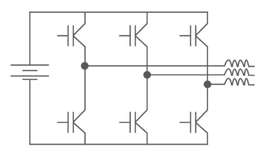
Figure 2 Transformer Based
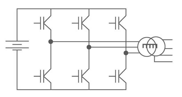
Figure 2 Transformer less Inverter
Figure 2 shows the configuration of Inverter with transformer and in a transformer less or transformer free configuration.
In transformer based inverter the primary objective of using a transformer is to setup the inverter output voltage as the DC bus voltage will be generally around 600V DC and the inductance required as a part of output LC filter will be incorporated in the same.
In a transformer less UPS, The DC bus voltage is increased to 800V DC and a DC-DC booster circuit will be introduced between the battery and the DC bus.
Refer section 5 for the details and selection of right topology based on the applications.
Also the actual inverter bridge can have two level switching or three level switching which is explained is detailed in the next section.
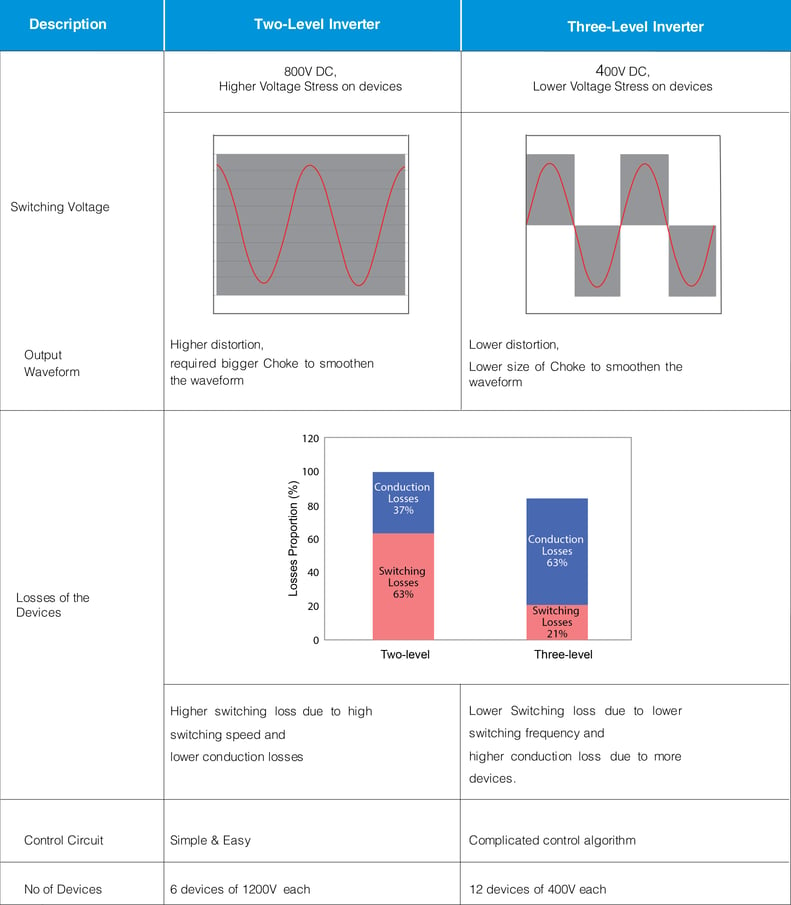
Two & three level inverter
Two-level inverter
The two-level inverter has been widely used for a range of power levels. The schematic of the topology is shown in Figure 3 and 4.The two-level inverter switches between two voltage levels of +Vdc and –Vdc. The switching voltage will be the full DC bus voltage which is generally 600 to 800Vdc which demands the usage of IGBT with higher voltageing of 1200V to reduce the impact of voltage stress.
As a result of PWM switching at higher frequency, the output voltage waveform generated contains higher distortion and which increases the size of the choke / inductor must be increased to smoothen it into a sinusoidal waveform.
The two-level inverter is a very simple design without any complex circuits. The two-level inverter will have a lower conduction loss but higher switching loss making the two-level inverter less efficient at higher switching frequencies.
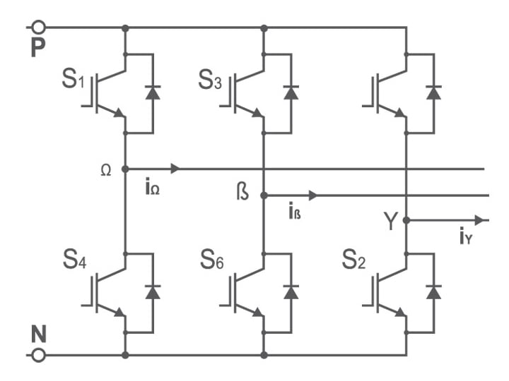
Figure 3 Two Level Inverter Bridge
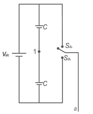
Figure 4 Symbolic Representation of two level inverter Bridge
Three-level inverter
The schematic of three level inverter is shown in 5 and 6. A three level inverter will have three switching states,+Vdc/2,0,-Vdc/2. The effective switching voltage of IGBT will be 400V and the IGBT voltages ratings will be 600V.However in a three level inverter we use 4 no’s of 600V IGBT in series for each leg.
As a result of Three level switching, the resultant output waveform is more sinusoidal with lesser distortion, which will reduce the size
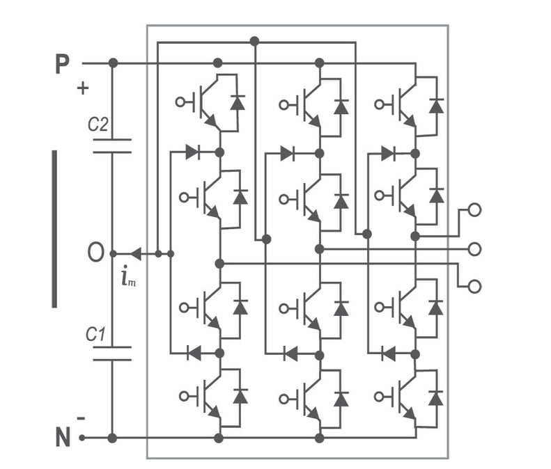
Figure 5 Three level Inverter Bridge
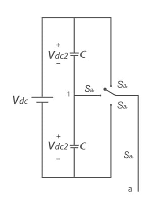
Figure 6 Symbolic Representation Of Three level Inverter Bridge
of choke/inductance required to smoothen the voltage waveform eventually reducing the losses across the chokes.
The switching losses of a three-level inverter is lesser but the conduction losses are higher compared to a two level inverter.
In a three level inverter, while the number of switching devices are more, the overall efficiency of the inverter can be better than a two level inverter. But actual efficiency of either topology depends on the IGBT used, the switching frequency as well as the losses in the output choke (Inductor).
Comparison of Two level inverter and three level inverter
Energy storage
When electrical service is disrupted (i.e., mains failure), the UPS continues to support the load connected to it through its energy storage system. The UPS may provide power for durations ranging from 10 to 20 seconds to several hours. Shorter duration UPSs are designed to carry the load during the start-up of back-up electrical generators, typically diesel engine driven generators, and to enable a smooth transition to the generator as the power source.
In many cases, the UPS is designed to provide power for 5 to 30 minutes. The purpose is to enable an orderly shutdown of operations thereby avoiding an abrupt shutdown, which would otherwise cause equipment damage, product/work losses or a security/safety hazard. The under-desk UPS for PCs is an example.
UPS with enough energy to provide power for several hours are somewhat rare. A key reason is that, in most situations, it is less expensive to store energy in the form of diesel fuel (for generators) if backup power is needed for several hours.
There are different technologies of energy storage solution available in the market like
a) Battery
b) Flywheels
c) Ultra capacitors
The selection of right energy storage system depends on
- Required Runtime/backup time
- Power density/Footprint
- Weight
- Lifespan / Cycle count
- Reliability
- Cost of Ownership (Initial cost /Maintenance cost)
- Operating temperature
Energy storage system – battery
Battery is the most critical component in the UPS and is also considered as heart of the UPS System. Without battery the UPS is just a power conditioner.
The purpose of the battery is to provide the energy necessary to supply the load when the mains supply in not available.
Cost of battery is a major component on the final price of the UPS solution proposed to the customer.
A battery is an electrochemical device that stores energy at one time for use at another. The battery uses electrical energy to store energy in chemical form which is converted to electrical energy during the discharge of the battery.
The UPS battery may furnish power to the inverter for a few seconds, many minutes, or hours. The battery capacity is determined by the amount and duration of power the inverter has to deliver to the load from the battery.
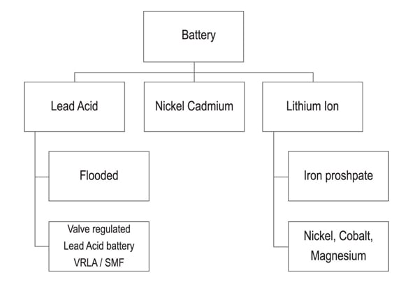
Types of battery
Three common varieties of battery chemistries popularly used in UPS applications are:
a) Lead Acid
b) Nickel Cadmium
c) Lithium Ion
Lead acid battery
The storage battery or secondary battery is such battery where electrical energy can be stored as chemical energy and this chemical energy is then converted to electrical energy as and when required. The conversion of electrical energy into chemical energy by applying external electrical source is known as charging of battery. Whereas conversion of chemical energy into electrical energy for supplying the external load is known as discharging of secondary battery. During charging of battery, current is passed through it which causes some chemical changes inside the battery. This chemical changes absorb energy during their formation.
When the battery is connected to the load, the chemical changes take place in reverse direction, during which the absorbed energy is released as electrical energy and supplied to the load. Now we will try to understand the principle working of lead acid battery and for that we will first discuss about lead acid battery which is very commonly used as storage battery or secondary battery
The main active materials required to construct a lead acid battery are
- Lead peroxide (PbO2)
- Sponge lead (Pb)
- Dilute sulfuric acid (H2SO4)
The positive plate is made of lead peroxide. This is dark brown, hard and brittle substance. The negative plate is made of pure lead in soft sponge condition. Dilute sulfuric acid used for lead acid battery has ratio of water to acid = 3:1.
During discharging
- Both of the plates are covered with PbSO4
- Specific gravity of sulfuric acid solution falls due to formation of water during reaction at PbO2 plate.
- As a result, the rate of reaction falls which implies the potential difference between the plates decreases during discharging process.
During charging
- Lead sulfate anode gets converted into lead peroxide.
- Lead sulfate of cathode is converted to pure lead.
- Terminal potential of the cell increases.
- Specific gravity of sulfuric acid increases.
The lead acid battery are further classified as
- Sealed maintenance Free (SMF) VRLA Battery
- Tubular/Flooded Battery
- Tubular GEL VRLA
Leed acid & ni-cd battery
SMF (Sealed Maintenance Free): battery is a battery which doesn’t require topping up due to negligible water loss. It is designed in such a way that it cannot be opened or refilled. These batteries are safe, maintenance free and are suitable for most UPS applications. The SMF battery will have an additional safety valve which release the excessive formation of hydrogen, as a result of overcharging, in to the atmosphere.
SMF battery works on a recombination technology where the hydrogen gas evolved during the charging process is converted to water with the help of oxygen present inside the battery container.
The typical cyclic performance of the battery is less and is limited by the operating temperature and the charging profile. The SMF battery delivers higher power at higher temperatures but the life of battery comes down significantly
The SMF battery needs to be installed in a controlled environment to maintain the temperature at 25-27 deg C and an additional hydrogen sensor in the battery room is recommended for installation.
Tubular batteries: have openings at top to add distilled water for maintenance and safe running. These batteries are very rugged and used in Cyclic application. These batteries last longer due to robust design and are suitable for harsh environment applications.
The tubular battery can be installed in any environment(other than closed air conditioner room) with proper ventilation and air exchanges as hydrogen evolution from the battery is higher when compared with SMF buttery.
Tubular GEL batteries require no topping of water and is a sealed, valve regulated lead-acid deep cycle battery that uses a gel electrolyte. These type of batteries are rugged and suitable for cyclic applications but are maintenance free compared to flooded tubular batteries.
Nickel cadmium cell (NiCd): The active components of a rechargeable Ni- Cd battery in the charged state consist of nickel hydroxide (NiOOH) in the positive electrode and cadmium (Cd) in the negative electrode. For the electrolyte, usually caustic potash solution (potassium hydroxide) is used. Due to their low internal resistance and the very good current conducting properties, Ni-Cd cells can supply extremely high currents and can be recharged rapidly.
These cells can operate over a large temperature range, from +60°C down to -20°C. The selection of the separator (nylon or polypropylene) and the electrolyte (KOH, LiOH, NaOH) is also of great importance. These constituents influence the voltage conditions in the case of a high current discharge, the service life and the overcharging capability of the cell. In the case of misuse, a very high-pressure may arise quickly.
For this reason, these cells are equipped with a reversible safety valve, which can act several times. NiCad cells offer a long service life (depending on the type of application and charging unit up to 2000 cycles).
Advantages and limitations of lead acid batteries & ni-cd
Comparing different types of battery
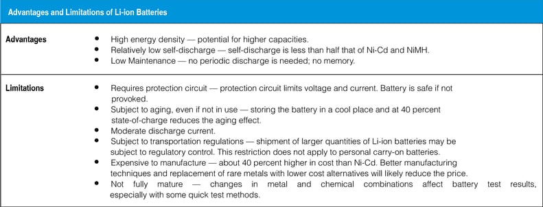
Lithium ion battery
Lithium ion batteries offer several advantages over traditional valve-regulated, lead acid batteries commonly used in UPS’s today. A much longer life span, smaller size and weight, faster recharge times, and declining prices have made lithium-ion batteries an appealing energy storage technology option for energy storage.
Similar to the lead- and nickel-based architecture, lithium-ion uses a cathode (positive electrode), an anode (negative electrode) and electrolyte as conductor. The cathode is a metal oxide and the anode consists of porous carbon. During discharge, the ions flow from the anode to the cathode through the electrolyte and separator; charging reverses the direction and the ions flow from the cathode to the anode.
When the cell charges and discharges, ions shuttle between cathode (positive electrode) and anode (negative electrode). On discharge, the anode undergoes oxidation, or loss of electrons, and the cathode sees a reduction, or a gain of electrons. Charge reverses the movement.
All materials in a battery possess a theoretical specific energy, and the key to high capacity and superior power delivery lies primarily in the cathode. For the last 10 years or so, the cathode has characterized the Li-ion battery.
Common cathode material include:
- Lithium Cobalt Oxide (or Lithium Cobaltate),
- Lithium Manganese Oxide (also known as spinel or Lithium Manganate),
- Lithium Iron Phosphate,
- Lithium Nickel Manganese Cobalt (or NMC) and
- Lithium Nickel Cobalt Aluminum Oxide (orNCA)
Different technologies of lithium ion battery

Energy storage system – flywheel
Flywheel stores electrical energy in the form of kinetic energy during charging process and during the discharging the kinetic energy is converted into electrical energy.
A typical system consists of
- a rotor suspended by bearings inside a vacuum chamber to reduce friction, connected to a combination electric motor/electric generator.
- First generation flywheel energy storage systems use a large steel flywheel rotating on mechanical bearings. Newer systems use carbon-fiber composite rotors that have a higher tensile strength than steel and are an order of magnitude lighter.
- Magnetic bearings are necessary; in conventional mechanical bearings, friction is directly proportional to speed, and at such speeds, too much energy would be lost to friction.
The flywheel has a vacuum chamber on which a motor is held in a magnetic bearing. During charging process, the motor rotates at 1000rpm in clock wise direction to store the electrical energy in the form of kinetic energy. During discharge the motor acts as a generator and will convert the kinetic energy back to electrical energy
Energy storage system – super capacitors
SuperCaps (also known as ultracapacitors or electric double-layer capacitors) provide an alternative source of DC power to traditional rechargeable batteries. Supercapacitors are high density energy storage devices with a capacitance (energy density) of up to 10,000 times that of conventional electrolytic capacitors.
Supercapacitors or double layer capacitor store energy much in the same way as a conventional capacitor, hence the amount of stored energy can be described by: A double layer capacitor consists of two electrodes, a separator, electrolyte, two current collectors and housing.
A very high capacitance is obtained in this way. Super capacitors are suitable for high power applications and offer very quick response times and high efficiency. Disadvantages are comparatively low energy density, high self-discharge and high cost. Small units exists, lager sizes the under development. Typical power ratings are 1kW-250 kW and efficiencies in the ranges of 85-98%