India
India China
China Europe
 France
 Hong Kong
 Indonesia
 Japan
Japan Singapore
 Thailand
 USA
USA
Earthing system
In an electrical installation or an electricity supply system, an earthing system or grounding system connects specific parts of that installation with the Earth’s conductive surface for safety and functional purposes.
Earthing: is the connection of the exposed conductive parts of the installation by means of
protective conductors to the “main earthing terminal”, which is connected to an electrode in contact with the earth’s surface.
A protective earthing conductor (PE): avoids electric shock hazard by keeping the exposed-conductive surface of connected devices close to earth potential in fault conditions. In the event of a fault, a current is allowed to flow to earth by the earthing system. If this is excessive the overcurrent protection of a fuse or circuit breaker will operate, thereby protecting the circuit and removing any fault induced voltages from the exposed-conductive surfaces.
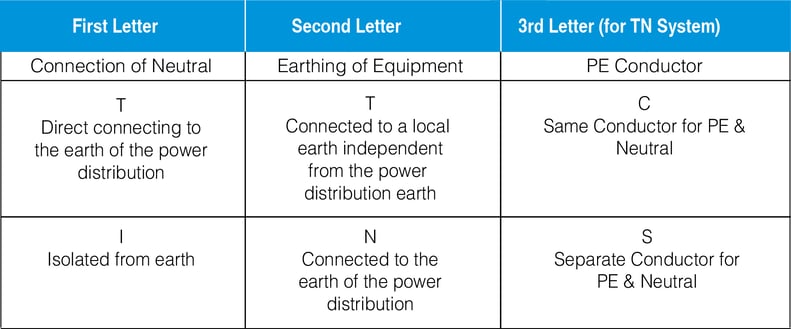
A functional earth: connection serves a purpose other than electrical safety, and may carry current as a part of normal operation. The most important example of a functional earth is the neutral in an electrical supply system when it is a current-carrying conductor connected to the earth electrode at the source of electrical power. International standard IEC 60364/ IS 3043 distinguishes three families of earth arrangements using the two letter codes TN, TT, and IT (three letter codes only for TN systems)
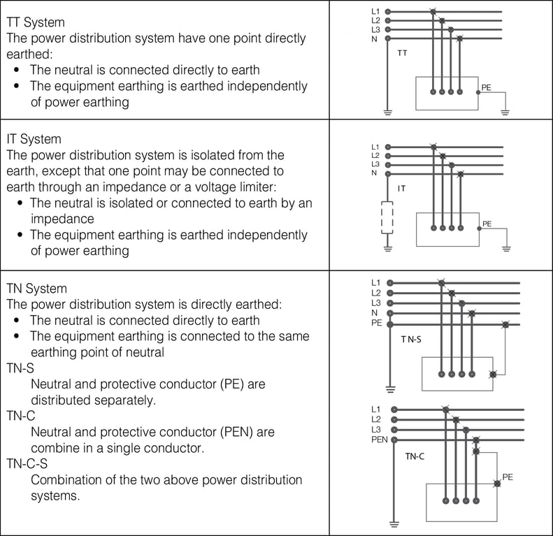
Types of Earthing System
Earthing principles of UPS system
Transformer-based/transformerless UPS with bypass
In this system Figure 1, the UPS Neutral Should not be bonded to the grounding conductor. This earthing configuration is similar for both transformer based / transformer less UPS and
- Does not change the upstream and downstream earthing system
- Does not provide any galvanic Isolation or
- Does not provide Common Mode Noise attenuation.
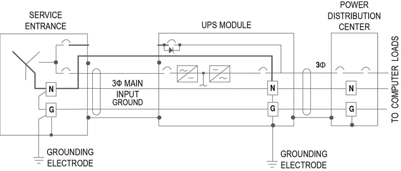
Figure 3 Transformerless UPS Without Bypass
Transformer-based UPS without bypass
In this system Figure 1, the UPS neutral should be bonded to the grounding conductor.
This earthing configuration
- Change’s the upstream and downstream earthing system
- Provides galvanic Isolation
- Provides Common Mode Noise attenuation.
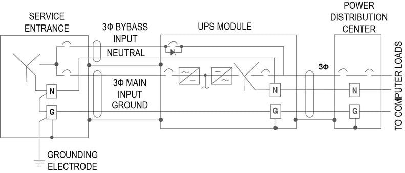
Figure 1 Earthing System- UPS With bypass
Transformerless UPS without bypass
In this system Figure 3, the UPS neutral should not be bonded to the grounding
conductor. This earthing configuration is similar for both transformer based / transformerless UPS with bypass and
- Does not change the upstream and downstream earthing system
- Does not provide any galvanic isolation or
- Does not provide Common Mode Noise attenuation.
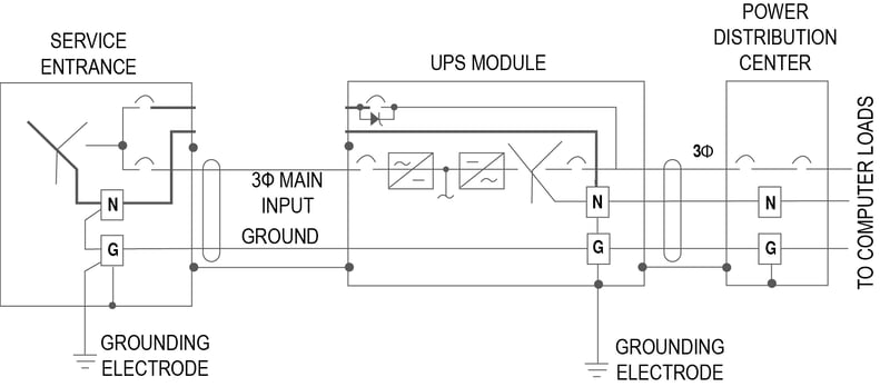
Figure 2 Transformer Based UPS Without Bypass
UPS with Isolated bypass
In this system Figure 4, a transformer is introduced in the bypass path of the UPS. The
output neutral of the UPS should be bonded to the grounding conductor. The UPS acts as a seperatively drived source. This earthing configuration
- Change’s the upstream and downstream earthing system
- Provides galvanic Isolation
- Provides Common Mode Noise attenuation.
Points to be taken care while earthing UPS
• Using of 4 Pole breakers at the input is prohibited as it breaks the input neutral which results in the floating of output neutral
• The output neutral of the UPS should not be earthed unless there is a transformer in the bypass or global input.
• The bypass mains and the rectifier mains has to be supplied with power from the same earthing system. If the earthing systems are different a transformer needs to be considered in bypass or rectifier input.
• In TNS system, the neutral earthing should be done only at one point(at source) only, multiple earthing is prohibited as per standards.
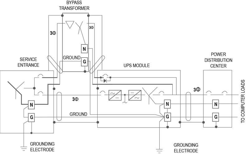
Figure 4 UPS with isolated bypass
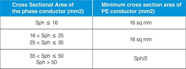
Selecting the earthing conductor size
Please see below the Earthing conductor size requirement. This is based on the standard IEC 60364-5-54