 India
India China
China Europe
 France
 Hong Kong
 Indonesia
 Japan
Japan Singapore
 Thailand
 USA
USA
Active Harmonic Filter
Introduction
There are a number of electrical devices that have nonlinear operating characteristics i.e even when applied voltage is sinusoidal in nature, the current drawn by the device is non-sinusoidal in nature. These nonlinear devices used in power distribution circuits create nonlinear currents and which subsequently causes voltage distortions. These nonlinear currents and voltages have been generally referred to as harmonic currents and voltages. The proliferation of electronic switching devices in modern equipment has resulted in a significant increase in the amount of harmonic pollution in the electrical distribution systems. These harmonics if disregarded or undetected may cause harmonic resonant conditions, which could present system operating problems resulting in complaints from customers and reduced life of power equipment as well as degraded efficiency and performance. Harmonic currents and voltages can cause many unfavourable effects on the power system itself and the connected loads. Malfunctioning of electronic equipment, capacitor failure, transformer and neutral conductor overheating, excessive heating in rotating machinery are some of these effects.
Harmonic currents are generated by non-linear loads like
- LED and CFL lighting,
- Switch Mode Power Supply (SMPS) units (computers, PLCs),
- Variable frequency drives used with motors
- UPS
- Arc furnaces & SCR temperature controllers Battery chargers & Rectifiers
Impact of harmonic
a. Grid side
- Reduction in efficiency of power generation, transmission, and utilization
- Aging of the installed electrical plant components and shortening of their useful life
- Reduced ability to transfer power (kW) through existing T&D infrastructure and transformers
- Overloading, overheating and failure of power factor correction capacitors, distribution transformers and neutral conductors.
- T&D capability in many parts of India has to be de-rated by upto 10% due to increasing level of harmonics generated from consumer side of meter
- Harmonics result in capacity reduction and higher fuel consumption for DG Sets or Captive Power Plants
b. Customer side
- Overheating of transformers, motors and cables
- Reduction in available capacity of transformers and switchgear
- Excess neutral currents
- Power factor capacitor failures
- Spurious operations of fuses, circuit-breakers and other protective equipment
- Increased failure of electronic devices
- Capacity limits on stand-by generators and UPS systems
- Higher losses in transformers, motors, cables leading to higher power bills
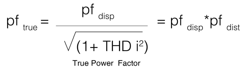
C. Power factor
The true power factor is the product of displacement & distortion power factor.If the harmonic distortion in more in the system, then the true power factor cannot be improved with just power factor correction capacitors. This can result in power factor penalties, loss of power factor incentives and higher electricity billing in locations with KVAh billing.
Harmonic study
The harmonic content varies from one installation to the other. This is based on the type of loads as well as the location of the loads in the power distribution system. A proper power quality audit of the site has to be conducted to understand the harmonic distortion levels in terms of current and voltage. The typical audit will document the following parameters to help propose the right solution to reduce the harmonics.
Reference standard for harmonic study
The limitation for injection of harmonic current into the mains is regulated by standards like
- IEEE Std. 519-1992: IEEE Recommended Practices and Requirements for Harmonic Control in Electric Power Systems
- Ministry of Power (Central Electricity Authority) Notification No: 12/X/STD(CONN)/GM/CEA (21-Feb-07)
- The Central Electricity Authority (Technical Standards for Connectivity to the Grid) Regulations, 2007
- Part IV: Grid Connectivity Standards applicable to the Distribution Systems and Bulk Consumers
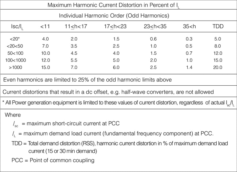
Figure 2 Harmonics Limits as per IEEE 519
The above figure 2 shows the harmonic current limits as specified by IEEE 519.
The intent of IEEE to specify this limits is to:
- Limit the harmonic current injection from customers so that they will not cause voltage distortion on the mains power supply
- Limit the overall harmonic voltage distortion of the mains voltage provided by the power supplier
These limits were intended to be applied at the point of common coupling between the customer and the utility mains
The harmonic limits are specified based on
- The ratio of Isc/IL
- Total Demand Distortion(TDD)
a. PCC – Point of common coupling
Point of Common Coupling (PCC) with the consumer/utility interface is the closest point on the utility side of the customer’s service where another utility customer is or could be supplied.
b. Ratio of Isc/IL
Isc is the maximum short-circuit current at the PCC which is basically a three-phased bolted short circuit current and ILis the maximum demand load current at the PCC. This maximum demand current value is established at the point of common coupling and should be taken as the sum of the currents corresponding to the maximum demand measured in the electricity meter during each of the twelve previous months divided by 12.
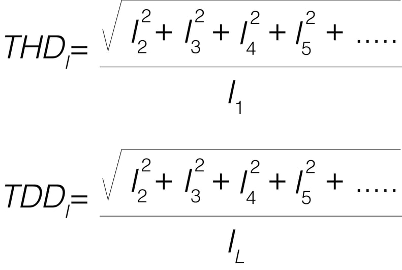
c. TDD–Total demand distortion
Total Demand Distortion (TDD) is almost similar to Total Harmonic Distortion (THD). The THD is calculated based on the momentary content of harmonic current compared to the momentary fundamental current whereas Total Demand Distortion (TDD) is calculated based on the momentary content of harmonic current compared to maximum demand load current at the PCC.
Connection principles
The Active Harmonic Filter is the proven solution to supply the harmonic currents required by the nonlinear loads and has been proven to be effective for applications across industries to help customers meet the IEEE and CEA guidelines. The Active Harmonic Filter is connected in parallel (shunt) with each of three phase conductors of a 3-phase, 3-phase, 4-wire electrical power system.
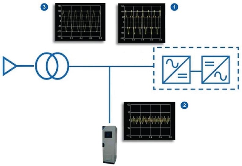
The active filter shall be suitable for connection at an electrical distribution panel, transformer secondary or at an individual load. The AHF will be installed in parallel to the harmonic generating loads. CT connected to the distribution system has to measure the current being drawn by the load and should feed a compensation current into system based on the actual current for amplitude & harmonic order, whose amplitude and individual harmonic order is exactly equal to the current drawn by the load, but which is 180 degree out of phase with it. So the harmonic currents are cancelled.
Application of Active Harmonic Filters
An Active Harmonic Filter (AHF) provides an effective means to mitigate harmonics, reduce process-related voltage fluctuations and improve equipment operating life and system capacity. It can be part of a power factor correction and harmonic filtering system.
a. Power factor improvement
The apparent power (Kilovolt Amperes or KVA) used in an electrical system by an industrial or commercial facility has two components:
- Real Power (Kilowatts or kW) which produces work
- Reactive Power (Kilo Volt Amperes Reactive or KVAr) which generates the magnetic fields required
- In inductive electrical equipment (AC motors, transformers, inductive furnaces, ovens, etc.)
The relationship between kVA, kW and KVAr maybe is represented by triangle as follows
kVA2 = kW2 + kVAR2
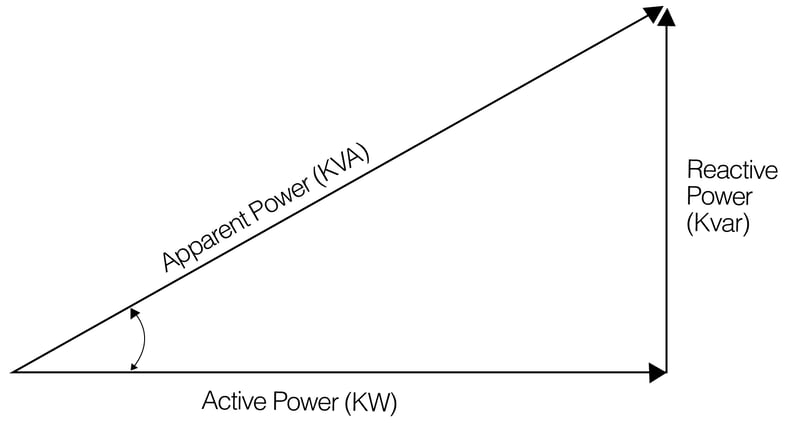
The ratio of Real Power (kW) to Total Power (kVA) is called the Power Factor (PF = kW / kVA)
The best way to improve the power factor is to reduce the KVAr consumption by injecting the required KVAr locally at the PCC. In case of harmonic rich installations, the power factor is based on the displacement and distortion factor as explained in section 2.c.
In most of the installations, the customer uses power factor correction capacitors for power factor improvement and the Active Harmonic Filters are mostly used for reducing the total harmonic distortion The Active Harmonic Filters have the ability to improve displacement power factor by injecting the required reactive currents if the feature is enabled. Further the Active Harmonic Filter can also improve the distortion power factor by countering and cancelling the harmonic currents.
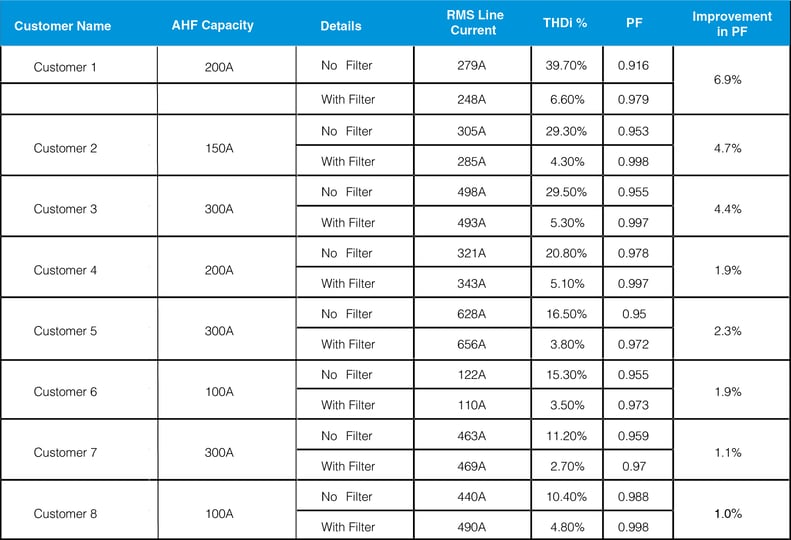
Improvement of true power factor by harmonic current (THDi) reduction is demonstrated in several sites. Higher the original THDi, more is the true power factor improvement when THDi is reduced by using an Active Harmonic Filter as measured in several customer sites in the table below.
Case study – food processing industry
The customer is a major food processing unit based out of Coimbatore (a city in southern part of Tamil Nadu) who produces tasty and healthy dairy products and other food range of ‘Ready to cook’ Instant Mixes’.
a.Challenges faced
Customer were facing challenges due to harmonics like
- Regulations of DISCOMs to restrict the current harmonic (THDi) to
- Frequent failures of electronic components
- Increased losses and higher temperature on cables and transformer
b. Solution proposed
We performed a load study to understand the harmonic content and the summary of our findings are as below
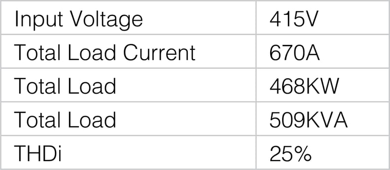
Thee customer wanted to reduce the THDi to less than 8% and we proposed the customer to install anactive
harmonic filter of 200A at the PCC.
Case study – IT/ITES industry
The customer is an Indian multinational provider of Information Technology (IT), networking technology solutions and Business Process Outsourcing (BPO) to the telecommunications industry.
a. Challenges faced
Customer was facing challenges like
- Regulations of DISCOM to restrict the current harmonic to less than 8%
- Low power factor
- Increased losses and high temperature on cables and transformers
b. Solution proposed
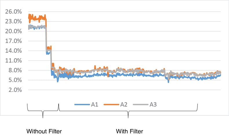
We performed a load study to understand the harmonic content and observed that the harmonic content was around 24%, predominantly 5th harmonic, refer figure 7
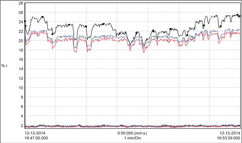
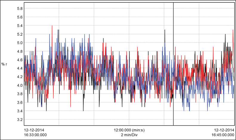
and we recommended to install a 75A Active Harmonic Filter to reduce the THDi to less than 5% (refer figure 8)
Case study textile industry
The customer is one of the leading suppliers of premium quality yarn supplier in South India. The manufacturing plant is located at Tamil Nadu, South India. The company is incorporated in 1992 with a well laid out building with latest machineries and modernizing periodically to meet the market requirements.
The Mill is equipped with the following Machineries
- Lakshmi Rieter & Trumac Blow rooms
- C1/3, LC 300 A & DK 780 Cards
- RSB 851 & Rieter D 30 Draw frames
- LR E7/4, Rieter E 62 & Lakshmi LK 54 Combers
- Lakshmi LF 1400 Simplex
- LR G5/1, Lakshmi Rieter LR6 & KTTM RXI 240 Ringframes
- Schlafhorst 338, Murata 7V, Murata 21C, Murata QPro & FPro Autoconers
a. Challenges Faced
Customer was facing challenges like
- Regulations from DISCOM to restrict the current harmonic to less than 8%
- Frequent failures of capacitor banks
- High temperature of distribution transformers
b. Solution proposed
We performed a load study to understand the harmonic content and observed that the harmonic content was around 12% predominantly 5th harmonic, refer figure 9 and based on our study we recommended an 600A filter to reduce the harmonic distortion to less than 3%,refer figure 10
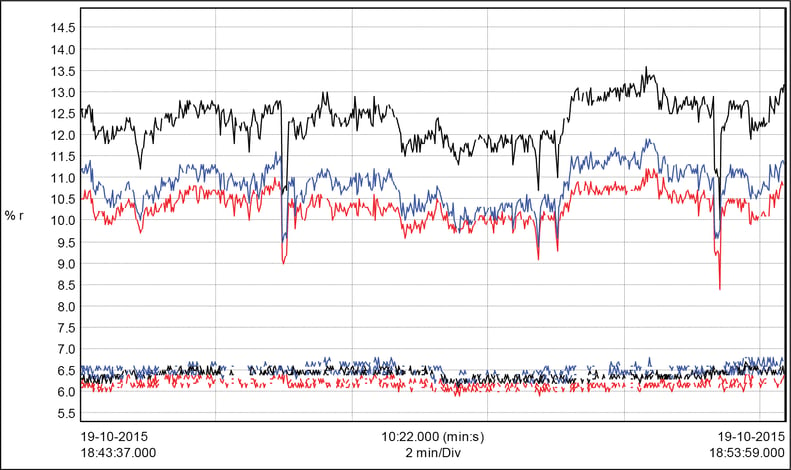
Figure 9 Harmonic percentage before installing Active Harmonic filter
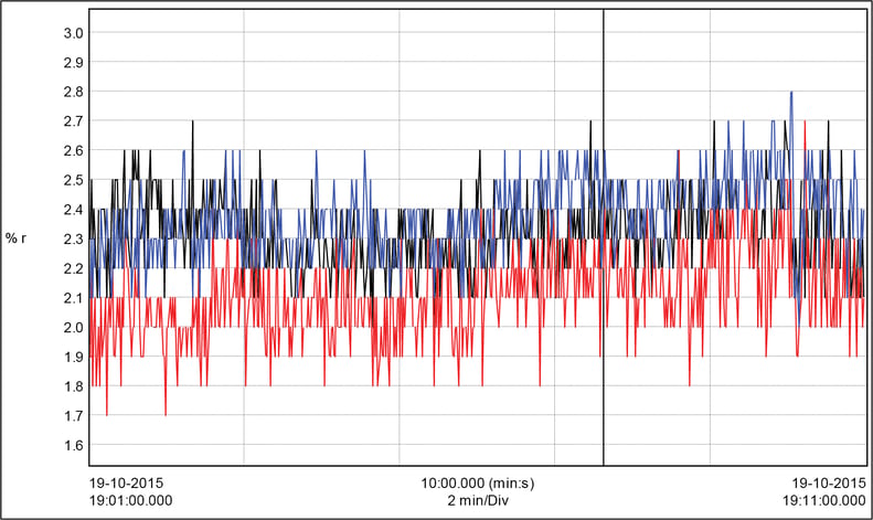
Figure 10 Harmonic Percentage after installing Active Harmonic Filter
Conclusion
By installing Active Harmonic Filter, the customer has benefited by:
- Reduction in total harmonic distortion being injected in the grid thus avoiding any future penalty
- levied on THD limits by state electricity Distribution Company
- Reduction in humming noise at the capacitor bank and its failure
- Improvement in true power factor
- Reduction in losses of distribution transformers
- Improvement in true power factor