 India
India China
China Europe
 France
 Hong Kong
 Indonesia
 Japan
Japan Singapore
 Thailand
 USA
USA
Sizing calculation
Prior to selecting the UPS, it is necessary to determine the need. UPS may be needed for a variety of purposes such as lighting, startup power, transportation, mechanical utility systems, heating, refrigeration, production, fire protection, space conditioning, data processing, communication, life support, or signal circuits.
Some facilities need an UPS for more than one purpose. It is important to determine the acceptable delay between loss of primary power and availability of UPS power, the length of time that emergency or backup power is required, and the criticality of the load that the UPS must bear. All of these factors play into the sizing of the UPS and the selection of the type of the UPS
Selection of UPS 3 Phase or 1 Phase
Single Phase power is used in most homes and small businesses and adequate for running lights, fans, 1 or 2 ACs, some computers and motors up to about 5 horsepower; a single phase motor draws significantly more current than the equivalent 3-Phase motor, making 3-Phase power a more efficient choice for industrial applications
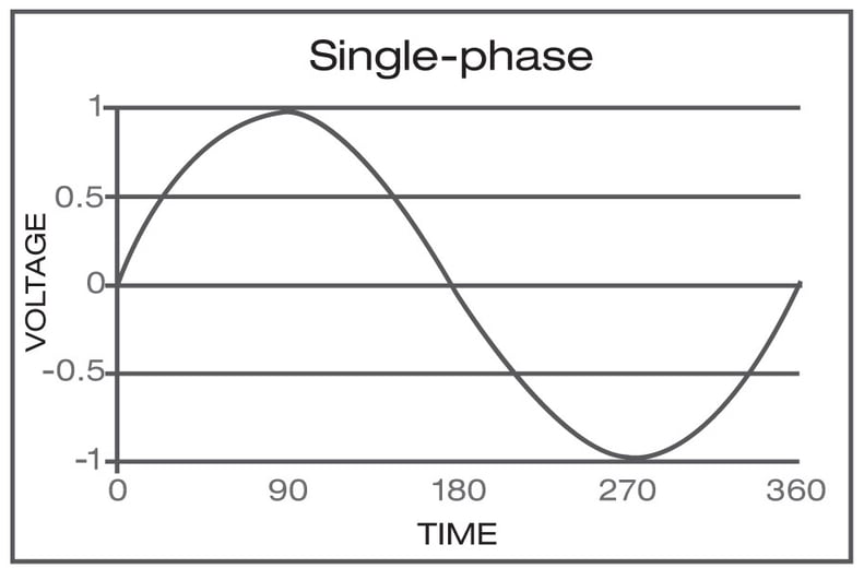
Figure-1 With the waveform of single-phase power, when the wave passes through zero, the power supplied at that moment is zero. The wave cycles n50 times per second
3-Phase power is common in large businesses, data centers, as well as industry and manufacturing around the globe. While it is expensive to convert to three phase from an existing single Phase installation, 3-Phase allows for smaller, safer and less expensive wiring.
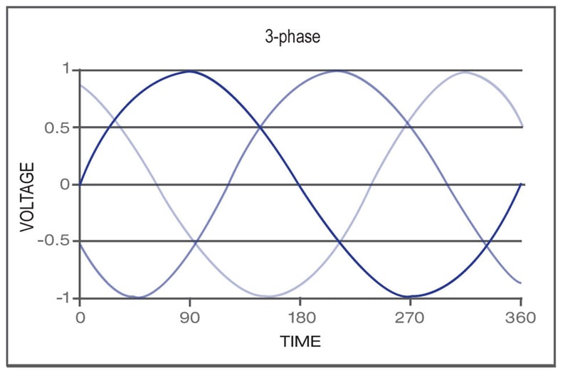
Figure-2 3-Phase power has 3 distinct wave cycles that overlap. Each phase reaches its peak 120 degrees apart from the others so the level of power supplied remains consistent
Most consumers of electricity in India have a three phase mains connection if the total load is more than 5-7 KW. Only if expected load is below 5-7KW, then the consumer gets a single Phase connection. Even when the consumer has a three phase connection, the choice of three phase or single phase UPS depends on several factors like the loads to be connected to UPS and also electrical distribution within the facility from the building incomer, electrical switchgear and distribution units to the room the loads to be protected are within. This not only builds up a complete picture of the electrical circuits on-site. It also helps to determine whether to offer a three phase or single phase UPS system.
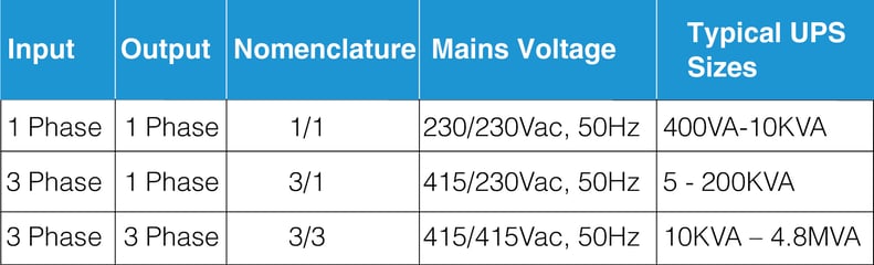
UPS Systems – Input and output phases
In UPS there are three potential phase configurations available. This is because a 3 phase mains or generator supply actually consists of three single phase supplies (and a neutral) with a 120 degree phase orientation between them. A 3 phase supply can deliver more electrical power than a single phase supply.
The laws of physics and Ohms Law also come into play, meaning that cable sizes also increase in diameter as amperages rise. A 10KVA output is generally the largest single Phase UPS system available. This is due to the output amperage and cable requirements. 10KVA=10,000VA / 230Vac = 43.5Amps.
In the world of UPS, it is common to refer to a single phase UPS only by its KVA/KW rating i.e. 5KVA. However for a three phase UPS it is common to refer to the KVA/KW rating along with the number of phases i.e. 20KVA 3/1 or 100KVA 3/3.
3 Phase UPS Systems (3/3 and 3/1)
Most datacentres, commercial and industrial buildings will have a 3 phase electrical incomer that connects them via a local distribution transformer to the Mains. Three phase circuits may be required throughout the building to carry the large amounts of electrical power required for large KVA three phase This is a generalisation as many environments can include both single and three phase loads of course.
From a UPS systems perspective, if we are to connect the UPS to a three phase supply we require a UPS with a 3/x configuration. If the loads are three phase as well, then we require a 3/3 configuration. If the loads are single phase we may need a 3/1 configuration.
Using a three phase UPS system can simplify a power continuity plan and allows a site to adopt a centralised power protection plan, where one large UPS is used to protect a complete building or critical circuits and operations within it. This is in contrast to a decentralised power continuity plan using a number of smaller UPS dispersed to protect clusters of loads like computers and lower power equipment (<10KVA) within a facility.
Single Phase UPS systems (1/1)
The wall sockets that we typically plug into are single phase supplies rated at 230Vac 50Hz in India. Typical examples would include ATMs, small lab equipments, desktop computers, file servers, switches, routers, hubs and telecoms systems.
Single Phase UPS systems up to 2KVA can be supplied with a plug or with covered terminals for hardwired installation. At 3KVA, the power required means that the UPS will be supplied as either a hardwired system or with a 16A plug. Above 5KVA to the largest single phase UPS system available (typically 10KVA) the UPS will require a hardwired installation and should also include an UPS maintenance bypass switch.
UPS System load sizing
When sizing UPS it is important to know the phase configuration required by both the mains supply and the loads, in addition to the overall load size. Electrical consultants and electrical contractors will often state both load size and phase configuration. An example would include ‘120KVA three phase’. This refers to a 120KVA load run from a three phase 415Vac, 50Hz supply. In terms of load sizing, this means that each phase (of the 3 phase electrical supply) will deliver up to 40KVA (or 174Amps at 230Vac). If the statement was 120KVA per phase then we would be looking at 3×120KVA per phase = 360KVA UPS load. The need for a 120KVA three phase UPS could be met with three single phase output 40KVA UPS provided the connected loads are single phase loads. These would be 3/1 configured and installed one per phase. However, the overall capital, installation and energy efficiency costs just rose by a factor of 3 compared to a single 120KVA UPS system installation. 3/1 UPS up to 60KVA are also used in office environment where the loads are single phase and this removes the need to balance the load connections in each of the three phases. Larger 3/1 UPS even up to 200KVA are typically required for DCS and SCADA loads in heavy industries like Power Plant, Steel Plant etc.
UPS Sizing steady state load conditions
Steady state loading conditions
As like any other power source, UPS is a limited power supply and the capacity of the UPS is defined in KVA(apparent Power) and KW (real power).
To arrive at the capacity of UPS and the configuration of UPS, the following steps needs to be followed
• Step 1 Need of Load
• Step 2 Configuration of UPS
• Step 3 Check on the KVA & KW demand supplied by the UPS
Step 1: Need of Load
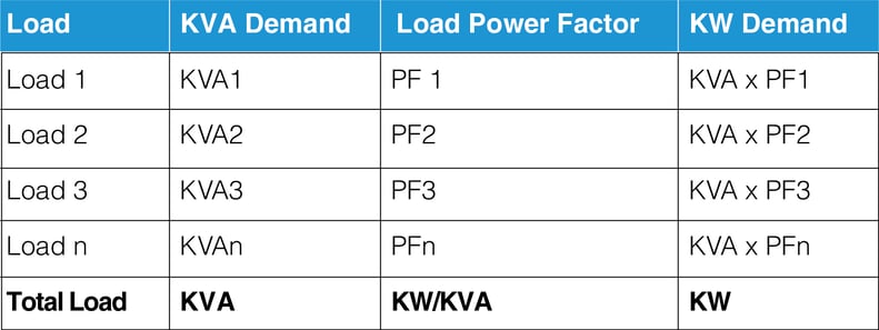
Tabulate the need of load as shown in the below table and arrive at the load demand of the loads expected to be connected to the UPS.
(Note: The load power factor has to be measured at the site or can be assumed based on the past experience)
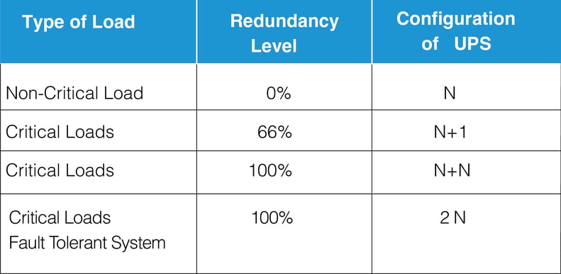
Step 2: Configuration of UPS
The criticality, of the loads will determine the necessary availability of the UPS. Based on the criticality the UPS capacity or configuration can be selected.
Where N is the no of UPS, required to support the Load. For critical load with 66% redundancy N>2, where a minimum of 2 UPS is required to support the load and 1 UPS for redundancy
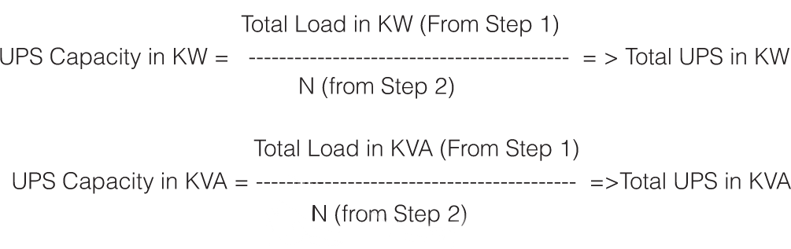
Step 3: Selecting the required UPS capacity
Based on the total demand and the configuration of UPS, the capacity of UPS is selected. The total load in KVA and KW derived in step 1 will have to divided by N as selected in step 2 to arrive the UPS capacity.
Ups sizing dynamic loading conditions
The sizing of UPS for loads which are dynamic in nature is a complicated subject, but with the recorded information as shown below, the optimised UPS capacity can be derived based on
• Inrush Current-Nature & Duration
• Peak Process Current–Nature & Duration
• Number of Loads, sequence of their operation
• Load Power Factor
• KVA and KW Demand of the UPS
Inrush current
Input surge current or switch-on surge is the maximum, instantaneous input current drawn by an electrical device when first turned on. The inrush current can be omitted in the selection calculation if the load is switched on only once and run continuously till the next shutdown of the plant as we can switch the loads in manual bypass and once the loads reach the steady state current, the loads can be transferred to the UPS.
If the loads are switched on & off repetitively then the UPS selection should include the inrush current also.
Peak process current
It is the maximum current drawn momentarily by the loads during the process time. This current can be repetitive in nature. The peak current has to be part of the UPS Sizing calculation irrespective of the nature and duration.
Number of loads and sequence of operation
The UPS selection depends on the no of loads, if there is only one load, then the selection of UPS is simple and is based on the maximum peak Current.
UPS Capacity in KVA = √3 X V X Irms-peak
If there are multiple loads with a combination of static and dynamic loading characteristic, then the UPS capacity is selected based on the sequence of operation of the loads.
Sequential operation of Load
When the loads are operated in sequence, the UPS capacity is selected based on the summation of rms currents of all the connected loads and the maximum rms peak current of the load as shown in the below formula UPS Capacity in KVA =√3 X VX ((∑1 N I rms)+ Imaxrms-peak)
Non-sequential operation of loads
When the loads are not operated in a sequence, the UPS capacity is selected based on the summation of rms currents of all the connected loads and the rms peak current of all the connected load as shown in the below formula
UPS capacity in KVA =√3 X V X ∑1n(Irms+ Irms-peak)
Battery sizing calculation
The purpose of the battery is to provide DC power to the inverter of the UPS when the mains fail and becomes an important component in the UPS system. There are different technologies of battery available in the market like Lead acid battery which is further classified as Tubular battery, Sealed Maintenance free(SMF,VRLA)Battery, Nickel Cadmium and Lithium Ion battery.
Sealed Maintenance Free, Valve Regulated Lead Acid (SMF VRLA Battery) is mostly used with the UPS systems today.
A VRLA battery utilizes a one-way, pressure-relief valve system to achieve a “recombinant” technology. This means that the oxygen normally produced on the positive plate is absorbed by the negative plate. This suppresses the production of hydrogen at the negative plate. Water (H2O) is produced instead, retaining the moisture within the battery. It never needs watering, and should never be opened as this would expose the battery to excess oxygen from the air.
• The nominal cell voltage of a battery cell is 2V, 6 cells are connected in series inside the battery container to have a final voltage of 12V.
• The capacity of the battery is defined as “Ampere Hour (AH)”.
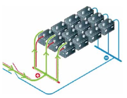
• The batteries are connected in series to increase the voltage of the battery bank and are connected in parallel to increase the capacity of the battery bank.
By design, the battery has to be operated in a controlled electrical and environmental conditions and the critical elements affecting battery life are:
1. Under charge Charging of battery with a lower voltage and current
2. Cycling Cyclic usage of battery
3. Overcharge Charging of battery with a higher voltage or current which is above the recommended conditions of the manufacturer
4. Temperature The ambient temperature
References
• IEEE 1184:2006 IEEE Guide for Batteries for Uninterruptible Power Supply Systems
• IEEE 485:1997 IEEE Recommended Practice for Sizing Lead-Acid Batteries for Stationary Applications
• Datasheet’s of major battery manufacturer’s
Life expectancy of smf vrla battery
Design life of battery
Design life is determined by the manufacturer and takes into account cell design and battery ageing under controlled conditions in the manufacturer’s lab. However, the design life of battery can be only used for reference as the real service life of battery depends on the various factor like
• Operating Temperature
• Number of charge, discharge cycle Paragraph Text
• Charging conditions
• Depth of discharge
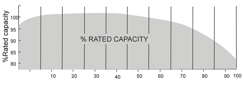
In simple terms, the battery will reach its end of life when its capacity falls below 80% of its rated capacity and warrants for immediate replacement.
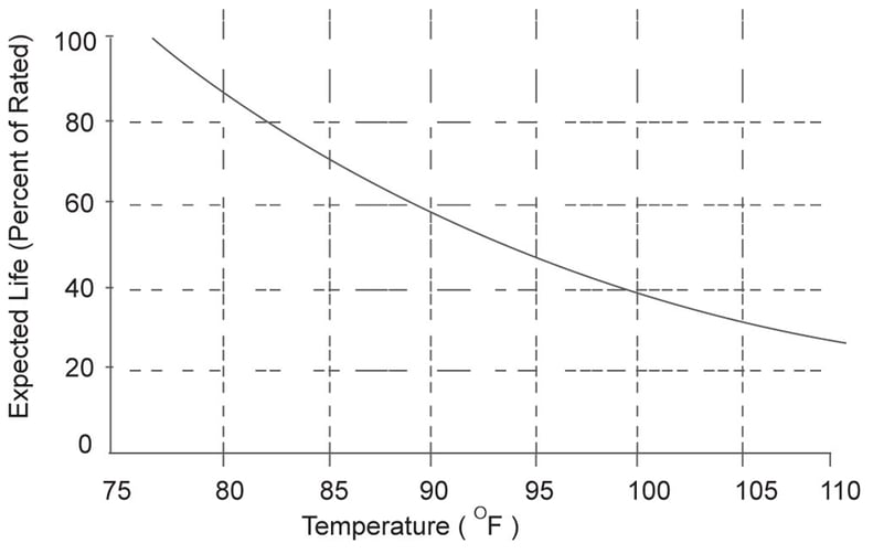
Impact of temperature on life of battery
The battery is rated in watts/cell at an ambient temperature of 25-27deg C. When the operating temperature or battery is less the capacity of the battery will be reduced and when the temperature is higher than the design temperature, the capacity of the battery increases.
Elevated temperature operation will shorten battery life. A general rule of thumb for lead-acid batteries is that the prolonged use at elevated temperatures will reduce the battery life by approximately 50% for every 8 ºC above 25 ºC
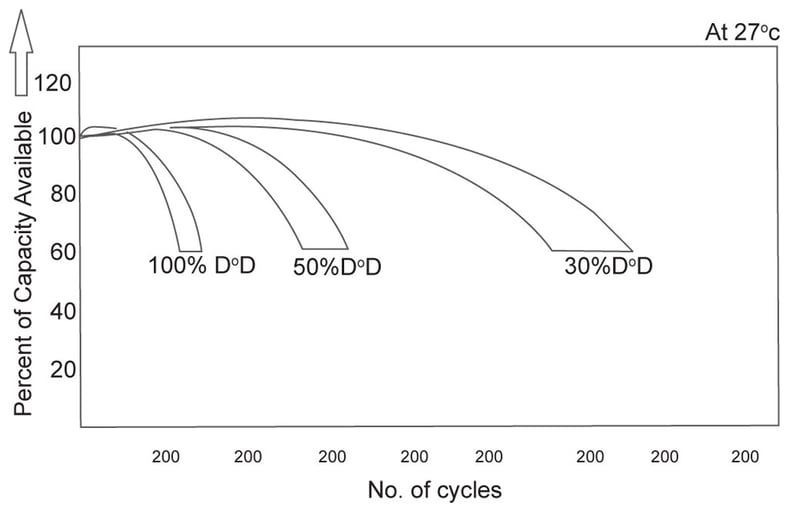
Frequency and depth of discharge
The life of a battery is related to the frequency and depth of discharges. A battery can provide more short duration, shallow cycles than long-duration, deep discharge cycles. Even momentary fluctuations in the AC power to the UPS may result in battery discharges for several seconds or more. Frequent cycling of the UPS battery, even for short durations, shortens battery life.
Considerations for battery sizing
Load profiling
Sizing a battery is important to ensure that the loads being supplied or the power system being supported are adequately catered for by the battery for a period of time (i.e. autonomy) for which it is designed. Improper battery sizing can lead to poor autonomy times, permanent damage to battery cells from over-discharge, and UPS shutdown due to low voltage.
The load profiling has to be done based on
• Nature of Loads to be supported by the battery
• Continuous
• Non-Continuous
• Momentary
• Battery autonomy time
• Design Margin
• Ageing Factor
• Effects of temperature
Design margin
Design Margin is considered to provide a capacity margin to allow for unforeseen additions of load to the UPS system and less-than optimum operating conditions of the battery due to improper maintenance, recent discharge, or ambient temperatures higher than anticipated, or a combination of these factors. A method of providing this design margin is by adding load of 10–15% to the battery sizing calculations.
Ageing factor
captures the decrease in battery performance due to age. The performance of a lead-acid battery is relatively stable but drops markedly at latter stages of life. The “knee point” of its life vs performance curve is approximately when the battery can deliver 80% of its rated capacity. After this point, the battery has reached the end of its useful life and should be replaced. Therefore, to ensure that battery can meet capacity throughout its useful life, an ageing factor of 1.25 should be applied (i.e. 1 / 0.8). There are some exceptions, check with the manufacturer.
Effects of temperature
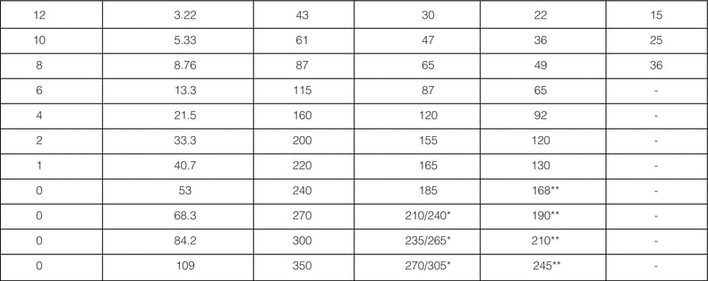
Temperature correction factor is an allowance to capture the ambient installation temperature. The capacity for battery cells are typically quoted for a standard operating temperature of 25 deg C and where this differs with the installation temperature, a correction factor must be applied. IEEE 485 gives guidance for vented lead-acid cells (see table), however for sealed lead-acid and Ni-Cd cells, please consult manufacturer for recommendations. Note that high temperatures, lower battery life irrespective of capacity and the correction factor is for capacity sizing only, i.e. you CANNOT increase battery life by increasing capacity.
Temperature correction factor for battery sizing
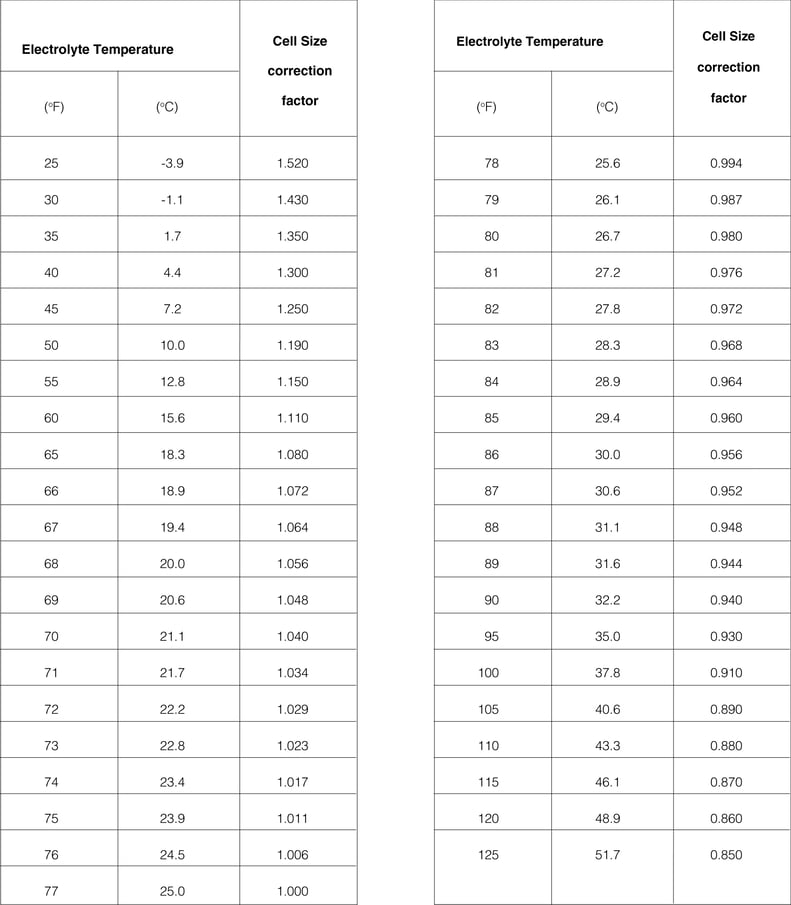
Note — This table is based on vented lead-acid nominal 1.215 specific gravity. However, it may be used for vented cells with up to a 1.300 specific gravity. For cells of other designs, refer to the manufacturer.
Battery sizing calculation for UPS systems
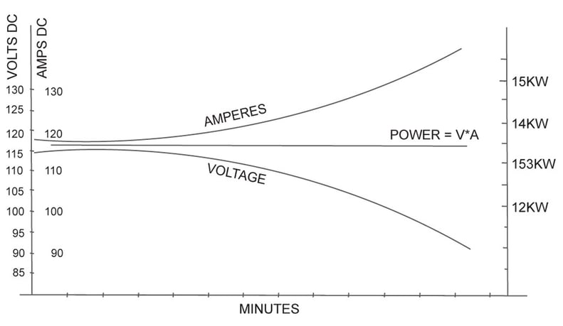
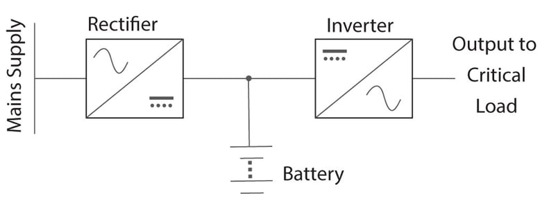
The inverter of UPS provides a constant voltage to the loads connected to it. During a battery discharge the battery supplies constant power to the inverter of the UPS. The DC input voltage to the inverter decreases during the discharge. To maintain a constant power output, the battery discharge current increases accordingly
There are different methods to connect the battery with the inverter of UPS. Battery can be connected directly to input of the inverter (refer Figure 8)
In this case, the load on the battery is purely based on the output load connected to the inverter and the losses of the inverter bridge.
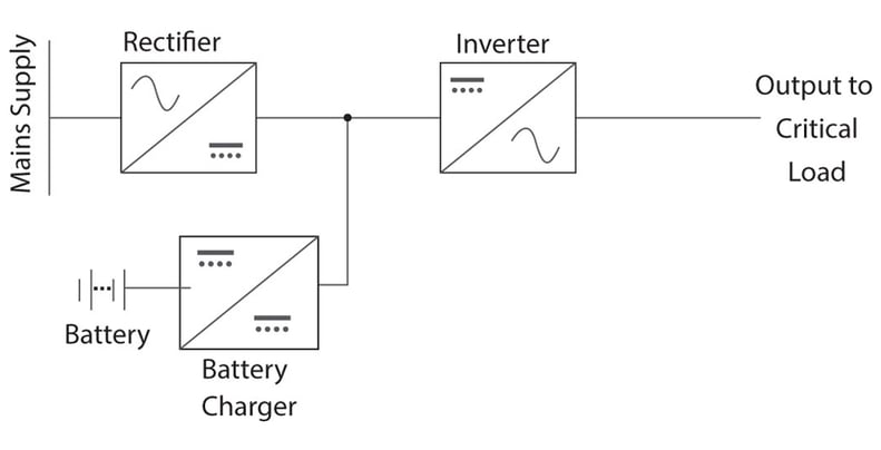
Battery is connected to a DC-DC Converter and the output of the DC-DC converter is connected as an input to the UPS (refer figure 9)
In this case, the load on the battery is based on the output load connected to the inverter, the losses of the inverter bridge and also the losses of the DC-DC Converter, which could increase the required battery capacity.
UPS Efficiency and power factor
UPS power ratings are quoted in volt-amperes (VA) and/or watts. The rating in watts is equal to the rating in volts-amperes multiplied by the power factor.
UPS output power rating in watts = UPS output in volts-amperes × power factor
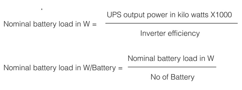
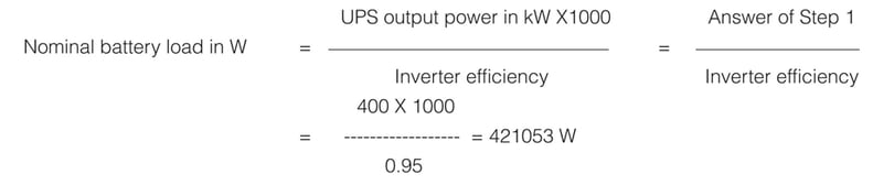
The battery load for sizing purpose is the UPS output rating in watts divided by the efficiency of the inverter. The efficiency should be based on rated UPS output
Battery sizing calculation
Adjusted battery load calculation
The nominal battery load should be adjusted for ageing and operating temperature conditions.
Battery Load in W/Battery = Nominal battery load in W/Battery × ageing factor × temperature correction factor x design margin
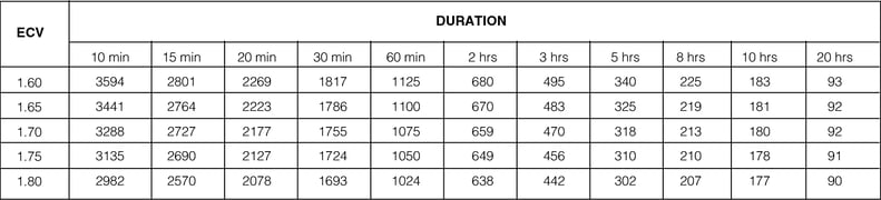
This final battery load in battery has to be cross referred with the battery manufacturer’s discharge characteristics for a specified battery autonomy time (sample table is shown in fig 10) with the required cut-off voltage to arrive at the capacity of the battery required.
General guidelines for battery selection
• Calculate the load in Watts-hours as accurate as possible.
• Include system losses due to efficiencies of power conditioning (inverter, battery charger – DC/DC converters).
• Include the appropriate factors: Temperature, autonomy, design margin, and depth of discharge (DOD), ageing factor
• Consider shallow DOD (max 20% recommended) and occasional deeper DOD (max 80%)
• Select highest battery capacities per unit to reduce the number of battery strings in parallel for better charge balance. The recommended maximum number of strings in parallel is 4.
Constant power discharge rating watts per battery @ 27 OC*
Sample calculation :
15 mins backup on a 500KVA UPS with an output power factor of 0.9
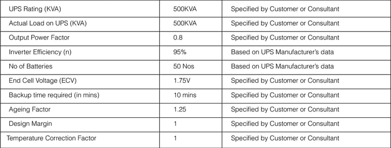
Step 1:
Arrive UPS output power rating in watts = UPS output in volts-amperes × power factor
= 500 X 0.8 KW = 400KW
Step 2:
Arrive the nominal battery load in W
Sample calculation
Step 3:
Arrive the nominal battery load in W per Battery

Step 4:
Arrive at the adjusted battery power required by taking into consideration design margin, ageing factor and TCF (Temperature correction factor)
Adjusted nominal battery load in W/Battery = Answer of Step 3 X Design Margin X Ageing Factor X TCF
= 8421.05 X 1 X 1.25 X 1
=10526 W/Battery
As the maximum available AH is 200AH Battery in 12V SMF VRLA battery, we need to parallel multiple strings of battery to achieve the desired backup time.
Step 5:

Hence in this scenario, 3 strings of 160AH battery with 50 battery in each string will provide 10 mins backup at end cell voltage of 1.75V/Cell.
Selection of cables
The cross section of cables depends on:
• Permissible temperature rise
• Permissible voltage drop
For a given load, each of these parameters results in a minimum permissible cross section. The larger of the two must be used.
When routing cables, care must be taken to maintain the required distances between control circuits and power circuits, to avoid any EMI disturbances caused by HF currents.
Temperature rise
Permissible temperature rise in cables is limited by the withstanding capacity of cable insulation.
Temperature rise in cables depends on:
- Type of core (Cu or Al)
- Installation method
- Number of touching cables type of cable, the maximum permissible current.
Voltage drops
The maximum permissible voltage drops are:
• AC circuits (50 or 60 Hz)
- If the voltage drop exceeds 3% (50-60 Hz), increase the cross section of conductors.
• DC circuit
- If the voltage drop exceeds 1%, increase the cross section of conductors.
Special case for neutral conductors
In three-phase systems, the third-order harmonics (and their multiples) of single-phase loads add up in the neutral conductor (sum of the currents on the three phases) For this reason, the following rule may be applied: neutral cross section = 2 x phase cross section in Sq mm
Output cables
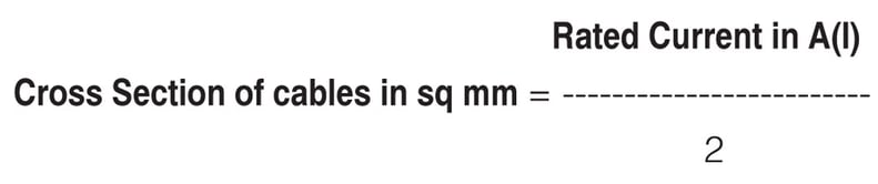
To arrive at the cross section of the cable, the output current needs to be calculated using the below formula

using the cable manufacturer’s datasheet and the conditions linked with routing and bunching of cables, the required cable can be selected.
As thumb rule, we can consider 2A/sq mm to arrive the cross section of the required cables.

Input, output and UPS to battery cables
Input Cables
The cross section of cables required for the input of the UPS can be derived using the same formula like output cables, but the input power in KVA needs to be derived based on the
- Connected Load
- Efficiency of the Inverter
- Battery charging Power
- Efficiency of Rectifier
- Input power factor of rectifier
- Minimum operating Voltage of Rectifier
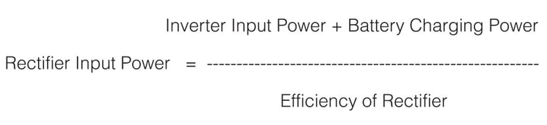
Step 1: Arrive at the input power of Inverter

Step 2: Calculate the battery charging power in W
Battery Charging Power = 2.2VX No of Cells X Charging Current
The charging current is typically 10% of AH Capacity
Step 3: Calculate the Input power of Rectifier in W
Step 4: Calculate the input current drawn
The rectifier input power calculated in step 3 needs to be converted to KVA by taking into consideration the input power factor
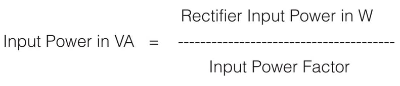

where Vph-ph is the minimum operating Voltage of rectifier
UPS to battery cables
The inverter of UPS provides a constant voltage to the loads connected to it. During a battery discharge the battery supplies constant power to the inverter of the UPS. The DC input voltage to the inverter decreases during the discharge. To maintain a constant power output, the battery discharge current increases accordingly.
The selection of UPS to battery bank cables has to be based on the current at minimum discharge voltage, which can be derived based on the below formula
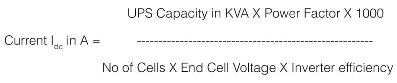
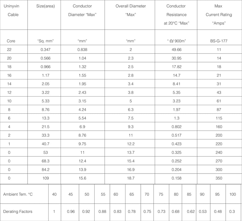
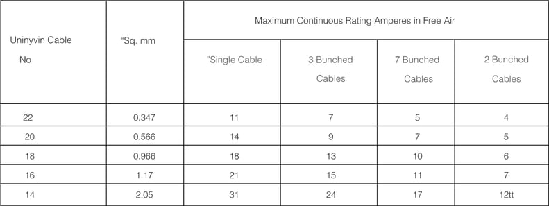
Uninyvin cables are generally preferred for cables between UPS & battery due to high current carrying capacity and smaller cross sectional area.
Cable datasheet
Selection of protections (circuit breakers or fuses)
Moulded Case Circuit Breakers are electro mechanical devices, which protect a circuit from Overcurrent and Short Circuit.
Their primary functions are to provide a means either to manually open a circuit and automatically open a circuit under overload or short circuit conditions. The overcurrent, in an electrical circuit, may result from short circuit, overload or faulty design.
MCCB is an alternative to a fuse since it does not require replacement once an overload is detected. Unlike fuse, an MCCB can be easily reset after a fault and offers improved operational safety and convenience without incurring operating cost.
Moulded case circuit breakers generally have a
- Thermal element for overcurrent and
- Magnetic element for short circuit release which has to MCCBs are now available with a variety of releases or operating mechanisms and these are given below
- Thermal Magnetic Release
- Electronic Release
- Microprocessor Release
Protections against short circuit
UPS is a limited power source, that is short circuit withstand capacity is also limited based on the selection of components.
One of the features that must be carefully evaluated when choosing a UPS is its capability to properly withstand a short circuit current on its output for a certain amount of time. This capability depends on whether the output short circuit current is withstood solely by the inverter or by the source through the static bypass In the first case, the capability strictly depends on the UPS design and in the second case it is based on the i2t characteristic of the SCR selected in the bypass path or fuse (if present in UPS)
When a short circuit happens on any one the distribution system on the output of the UPS, the current increases significantly. If the fault is not cleared within milliseconds, we might risk the uptime of other loads connected to the same UPS as the UPS or the upstream protection of the UPS will trip resulting in downtime of all the connected loads.
In practice, for a given prospective short-circuit current value, the minimum i2t let-through of the upstream device must higher be than the maximum i2t let-though of the downstream device. For protection of short circuit on the downstream, the UPS will be based under two conditions
- Short circuit current with bypass source available
- Short circuit current without bypass source
- Short circuit current with downstream transformer in PDU or global output of UPS
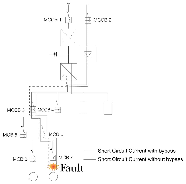
When a short circuit happens it will downstream the UPS, and the UPS will transfer the short circuit immediately to the static bypass as the static bypass will have a higher let-through energy(i2t).
In this scenario, let through energy(i2t) of the MCB 7 has to be lower than that of the breakers present in the upstream in to have a proper discrimination of the short circuit. If the MCB 6 has a lower let through energy(i2t) when compared with MCB 7, then we risk to lose all the loads connected to MCB6.
The let through energy(i2t) of MCCB2 is very important. If the let through energy of MCCB 2 is higher than what the SCR can handle, then the SCR will fail.
To protect the loads, SCR and to have the proper discrimination of short circuit, the following rule has to be respected
• i2tSCR> i2tMCCB2
• i2tMCCB3> i2tMCB6>i2tMCB7
Short circuit current without bypass
When the bypass is disabled or if the bypass source is not available and if short circuit happens downstream the UPS the inverter of UPS will support for a short duration before it trips because of electronic protections.
In this scenario, the i2t MCCB3>i2t MCB6>i2t MCB7 For the magnetic setting of MCCB’s & MCB’s has to be coordinated with inverter S.C current.
Short circuit current with transformer in pdu or global output of UPS
When a transformer is used either at the global output of the UPS or in a PDU, the transformer changes the short circuit discrimination of the downstream circuit. Now the UPS short circuit current has no relevance to fault discrimination.
The fault circuit current or the let though energy will purely depend on the impedance of the transformer.
The short circuit current of the transformer is the ratio of full load current of the transformer and its impedance. If we have transformer with a rated current of 200A and with an impedance of 5%, the short circuit current of transformer will be 4KA.
Protecting battery from short circuits
Short circuit protection in battery path
Battery is one of the vital components in an UPS system and its main purpose is to provide DC power to the inverter of the UPS when the mains fail and get charged through the rectifier when the mains return.
Like any other power source, battery will also contribute to the fault current when there is fault on the battery. The main parameters which contribute to magnitude of the current are battery’s internal resistance (this depends on plate surface area, internal plate spacing and electrolyte type) and its external circuit resistance. The short circuit current will vary based on the condition and the age of the battery.
Short circuit current of battery bank
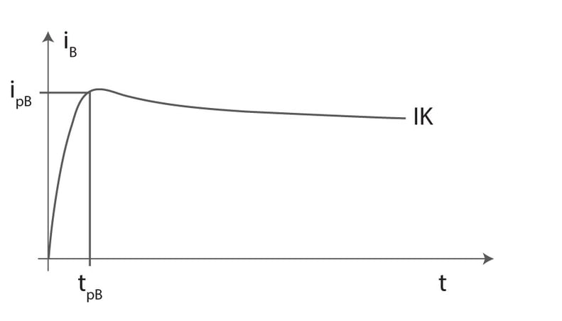
The short circuit current of the battery can be calculated based on the standard “IEC 61660-1, “short circuit currents in DC auxiliary installations in power plants and substations – part1: Calculation of short circuit currents”.
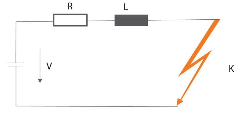
The following figure shows the curve of the short circuit current delivered by a stationary lead-acid battery; as it can be seen in the figure, after the time, and this is the time necessary to reach the peak, and the short circuit value decreases to the quasi steady-state short circuit current.
The short circuit current of battery can be calculated by using the Ohms Law(V=IR).
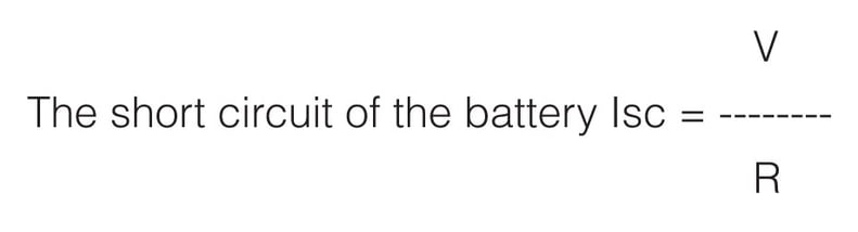
Where VOpen Circuit Voltage of the battery
RInternal Resistance of the battery
Co ordination of battery breaker
Selection of battery breaker capacity and its trip unit :The selection the battery breaker depends on parameters like
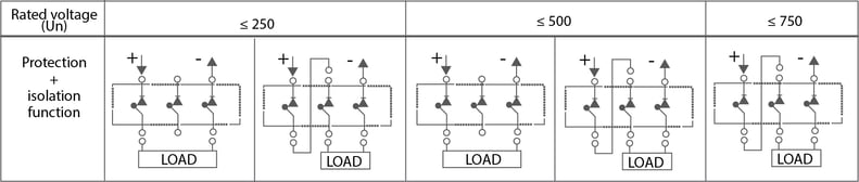
Operating voltage of the battery bank: Generally most of the breakers are designed with an voltage of 250V/Pole and based on the operating voltage of the battery bank, the poles has to be connected in series to achieve the desired voltage level as shown in fig.13
Nominal discharge current of the battery bank: This is the current which passes through the breaker under normal conditions of battery discharge
Short circuit current of the cattery bank: Most of the breakers have a thermal and a magnetic trip unit. While the thermal setting is used for overload protection, the magnetic setting is used for short circuit protection. When we discuss about battery protection, the magnetic setting of the breaker is used to disconnect the battery from the circuit when there is a short circuit. It is important to select the breaker with the right trip unit so that the battery is isolated when there is an fault.
Note: When an AC breaker is used for a DC applications a derating is applicable on the trip settings of the breaker.
Coordination of battery breaker with the battery fault current: Now that we have selected the right breaker for the battery protection, the most important task which lies ahead is to coordinate the battery breaker with the short circuit current of the battery As we said earlier, the short circuit current depends on the voltage and the internal resistance of the battery. The internal resistance increases with the ageing of battery under these conditions and the short circuit current decreases. If this short circuit current is less than the pickup value of the magnetic setting of the breaker the principle objective of using
the breaker is defeated as the breaker will not trip.
To overcome this issue, the magnetic pickup of the breaker trip unit is set at 70% of the nominal short circuit current so that even at low voltage or when the battery reaches the end of life, the battery breaker will do its job of “protecting the battery “
The magnetic setting(Im) of the breaker is < 70% of Isc of Battery